
Datasheet

General Description
The MAX4951 dual-channel buffer is designed to re-drive
serial-ATA (SATA) I and SATA II signals and is functional
up to 6.0Gbps for next-generation data rates. The
MAX4951 can be placed near an eSATA connector to
overcome board losses and produce an eSATA-compati-
ble signal level.
The MAX4951 preserves signal integrity at the receiver by
reestablishing full output levels, and can reduce the total
system jitter (T
J
) by squaring up the signal. This device
features channel-independent digital boost controls to
drive SATA outputs over longer trace lengths, or to meet
eSATA specifications. SATA Out-Of-Band (OOB) signaling
is supported using high-speed amplitude detection on the
inputs, and squelch on the corresponding outputs. Inputs
and outputs are all internally 50Ω terminated and must be
AC-coupled to the SATA controller IC and SATA device.
The MAX4951 operates from a single +3.3V (typ) sup-
ply and is available in a small, 4mm x 4mm, TQFN
package with flow-through traces for ease of layout.
This device is specified over the 0°C to +70°C operat-
ing temperature range.
Applications
Servers
Desktop Computers
Notebook Computers
Docking Stations
Data Storage/Workstations
Features
o Single +3.3V (typ) Supply Operation
o Supports SATA I (1.5Gbps) and SATA II (3.0Gbps)
o Supports up to 6.0Gbps for Next-Generation
Applications
o Meets SATA I, SATA II Input-/Output-Return Loss
Mask
o Supports eSATA Levels
o Supports SATA Out-of-Band (OOB) Signaling
o Internal Input/Output 50
Ω
Ω
Termination Resistors
o Inline Signal Traces for Flow-Through Layout
o ESD Protection on All Pins: ±5.5kV
o Space-Saving, 4mm x 4mm, TQFN Package
MAX4951
SATA I/SATA II Bidirectional Re-Driver
________________________________________________________________
Maxim Integrated Products
1
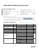
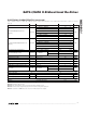
Ordering Information
19-4178; Rev 1; 5/09
For pricing, delivery, and ordering information, please contact Maxim Direct at 1-888-629-4642,
or visit Maxim’s website at www.maxim-ic.com.
+
Denotes a lead(Pb)-free/RoHS-compliant package.
*
EP = Exposed pad.
PART TEMP RANGE PIN-PACKAGE
MAX4951CTP+ 0°C to +70°C 20 TQFN-EP*
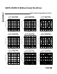
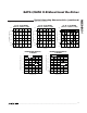
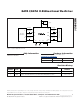
Pin Configuration
19
20
18
17
7
6
8
HAM
HBP
9
HAP
DAM
DBM
DBP
DAP
1 2
GND
45
15 14 12 11
GND
V
CC
BA
BB
EN
V
CC
MAX4951
GND
GND
3
13
GND
16
10
V
CC
V
CC
TQFN
4mm x 4mm
TOP VIEW
HBM
*EP
*CONNECT EXPOSED PAD (EP) TO GND.