
Datasheet


MAX530
+5V, Low-Power, Parallel-Input,
Voltage-Output, 12-Bit DAC
______________________________________________________________________________________ 13
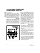
A0 = A1 = 0
A0 = A1 = 1
DAC UPDATE
NBH
NBL & NBM
CS
WR
LDAC = 0 (DAC LATCH IS TRANSPARENT)
Figure 8b. 8-Bit and 16-Bit µP Timing Sequence with LDAC = 0
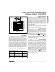
Unipolar Configuration
The MAX530 is configured for a 0V to +2.048V unipolar
output range by connecting ROFS and RFB to VOUT
(Figure 9). The converter operates from either single or
dual supplies in this configuration. See Table 3 for the
DAC-latch contents (input) vs. the analog VOUT (output).
In this range, 1LSB = REFIN (2
-12
).
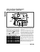
A 0V to 4.096V unipolar output range is set up by con-
necting ROFS to AGND and RFB to VOUT (Figure 10).
Table 4 shows the DAC-latch contents vs. VOUT. The
MAX530 operates from either single or dual supplies in
this mode. In this range, 1LSB = (2)(REFIN)(2
-12
) =
(REFIN)(2
-11
).
33µF
REFIN
REFOUT
AGND
DGND
REFGND
V
DD
V
SS
ROFS
RFB
VOUT
V
OUT
0V TO -5V
+5V
G = 1
MAX530
33µF
REFIN
REFOUT
AGND
DGND
REFGND
V
DD
V
SS
ROFS
RFB
VOUT
V
OUT
0V TO -5V
+5V
G = 2
MAX530
Figure 9. Unipolar Configuration (0V to +2.048V Output) Figure 10. Unipolar Configuration (0V to +4.096V Output)