
Datasheet


GATE Voltage
A curve of Gate Drive vs. V
CC
is shown in Figure 13.
GATE is clamped to a maximum voltage of 18V above the
input voltage. At a minimum input-supply voltage of 33V,
the minimum gate drive voltage is 10V. When the input
supply voltage is higher than 20V, the gate-drive voltage
is at least 10V and a standard n-channel MOSFET can be
used. Using the MAX5947 in applications over a 9V to
20V range, a logic-level N-FET must be used with a prop-
er protection Zener diode between its gate and source
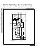
(see D1 in Figure 5).
Thermal Shutdown
If the MAX5933_/MAX5947_ die temperature reaches
+150°C, an overtemperature fault is generated. As a
result, GATE goes low and turns the external MOSFET off.
The MAX5933_/MAX5947_ die temperature must cool
down below +130°C before the overtemperature fault
condition is removed.
R6
1kΩ
5%
C1
10nF
D2
CMPZ5248B
Q1
IRF530
R5
10Ω
5%
R
SENSE
0.025Ω
R3
59kΩ
1%
R4
3.57kΩ
1%
R7
24kΩ
5%
C
L
R2
3.4kΩ
1%
R1
49.9kΩ
1%
C2
0.68µF
MAX5933B
MAX5947B
PWRGD
GND
V
IN
TIMER
ON
PWRGD
FB
GND
V
CC
SENSE GATE
5
1
3
2
4
876
D1
30V
1N5256B
SHORT
PIN
0.1µF
MAX5933A–MAX5933F/MAX5947A/B/C
Positive High-Voltage, Hot-Swap Controllers
12 ______________________________________________________________________________________
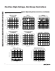
OVERVOLTAGE WAVEFORMS
I
SENSE
5A/div
TIMER
10V/div
IN
50V/div
GATE
50V/div
10µs/div
OUTPUT
50V/div
Figure 11. Overvoltage Waveforms
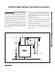
Figure 10. Overvoltage Detection