
Datasheet


MAX5933A–MAX5933F/MAX5947A/B/C
Positive High-Voltage, Hot-Swap Controllers
______________________________________________________________________________________ 13
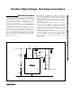
Layout Considerations
To achieve accurate current sensing, a Kelvin connec-
tion is recommended. The minimum trace width for 1oz
copper foil is 0.02in per amplifier to ensure the trace
stays at a reasonable temperature. However, 0.03in.
per amplifier or wider is recommended. Note that 1oz
copper exhibits a sheet resistance of approximately
530µΩ/square. Small resistances add up quickly in
high-current applications. To improve noise immunity,
connect the resistor-divider to ON close to the device,
and keep traces to V
CC
and GND short. A 0.1µF
capacitor from ON to GND also helps reject induced
noise. Figure 14 shows a layout that addresses these
issues. It is recommended that 2oz copper is used,
particularly as the external MOSFET must be thermally
coupled to the MAX5933_/MAX5947_ to ensure proper
thermal-shutdown operation.
R6
1kΩ
5%
C1
10nF
D1
CMPZ5248B
Q1
IRF530
R5
10Ω
5%
R
SENSE
0.01Ω
R3
143kΩ
1%
R4
4.22kΩ
1%
R7
47kΩ
5%
C
L
220µF
R2
10.2kΩ
1%
R1
294kΩ
1%
C2
0.68µF
MAX5933A
GND
V
IN
TIMER
ON
PWRGD
FB
GND
V
CC
SENSE GATE
5
1
3
2
4
876
SHORT
PIN
V
IN+
ON/OFF
V
IN-
V
OUT+
V
OUT-
V
OUT
0.1µF
GATE DRIVE vs. V
CC
V
CC
(V)
GATE DRIVE (V
GATE
- V
CC
) (V)
604020
2
4
6
8
10
12
14
16
0
080
Figure 13. Gate Drive vs. Supply Voltage
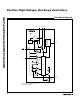
Figure 12. Active-Low Enable Module