
Datasheet
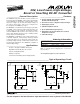

MAX629
28V, Low-Power, High-Voltage,
Boost or Inverting DC-DC Converter
_______________________________________________________________________________________ 5
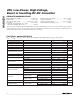
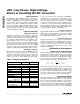
______________________________________________________________Pin Description
Current-Limit Set Input. Connect to V
CC
for a 500mA LX current limit, or connect to GND for a 250mA LX
current limit. See
Setting the Current Limit.
ISET5
GroundGND6
Feedback Input for setting output voltage. Connect to an external voltage divider. See
Setting the Output
Voltage.
FB4
1.25V Reference Output. Bypass to GND with a 0.1µF capacitor for I
REF
≤ 10µA. REF can source 100µA to
drive external loads. For 10µA ≤ I
REF
≤ 100µA, bypass REF with a 0.47µF capacitor.
REF3
PIN
Polarity Input. Changes polarity and threshold of FB to allow regulation of either positive or negative output
voltages. Set POL = GND for positive output voltage, or set POL = V
CC
for negative output voltage.
POL2
Active-Low Shutdown Input. A logic low puts the MAX629 in shutdown mode and reduces supply current to
1µA.
SHDN
1
FUNCTIONNAME
Internal N-Channel DMOS Switch DrainLX7
Power-Supply InputV
CC
8
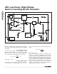
_______________Detailed Description
The MAX629 low-power, boost DC-DC converter pro-
vides either positive or negative output voltages up to
±28V from a wide range of input voltages. It is
designed primarily for use in low-power, high-voltage
applications such as LCD biasing and set-top box var-
actor tuning. The MAX629’s unique control scheme
provides high efficiency and a wide range of output
voltages with only 80µA quiescent supply current, mak-
ing it ideal for battery-powered applications. The inter-
nal N-channel DMOS switch has a pin-programmable
current limit (250mA and 500mA), allowing optimization
of output current and component size. Figure 1 shows
the MAX629 functional diagram.
Control Scheme
A combination of peak-current limiting and a pair of
one-shots controls the MAX629 switching, determining
the maximum on-time and constant off-time. During the
on-cycle, the internal switch closes, and current
through the inductor ramps up until either the fixed
10µs maximum on-time expires (at low input voltages)
or the switch’s peak current limit is reached. The peak
switch current limit is selectable to either 500mA (ISET
= V
CC
) or 250mA (ISET = GND) (see
Setting the
Current Limit
). After the on-cycle terminates, the switch
turns off, charging the output capacitor through the
diode. In normal operation, the minimum off-time is set
to 1µs for positive output voltages and 3.5µs for nega-
tive output voltages. When the output is well below reg-
ulation, however, the off-time is increased to 5µs to pro-
vide soft-start during start-up. The switching frequency,
which depends upon the load, can be as high as
300kHz.
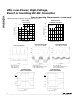
Shutdown Mode
When SHDN is low, the MAX629 enters shutdown
mode. In this mode, the feedback and control circuit,
reference, and internal biasing circuitry turn off. The
shutdown current drops to less than 1µA. SHDN is a
logic-level input; connect it to V
CC
for normal operation.
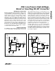
The output voltage behavior in shutdown mode
depends on the output voltage polarity. In the positive
output voltage configuration (Figure 2), the output is
directly connected to the input through the diode (D1)
and the inductor (L1). When the device is in shutdown
mode, the output voltage falls to one diode drop below
the input voltage, and any load connected to the output
may still conduct current. In the negative output voltage
configuration (Figure 3), there is no DC connection
between the input and the output, and in shutdown
mode the output is pulled to GND.
__________________Design Procedure
Setting the Output Voltage
For either positive or negative output voltage applica-
tions, set the MAX629’s output voltage using two exter-
nal resistors, R1 and R2, as shown in Figures 2 and 3.
Since the input bias current at FB has a 50nA maximum
value, large resistors can be used in the feedback loop