
Datasheet

MAX629
28V, Low-Power, High-Voltage,
Boost or Inverting DC-DC Converter
6 _______________________________________________________________________________________
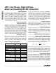
without a significant loss of accuracy. Begin by select-
ing R2 to be in the 10kΩ to 200kΩ range, and calculate
R1 using the applicable equation from the following
subsections.
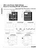
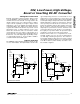
Positive Output Voltages
For positive output voltages, use the typical boost con-
figuration shown in Figure 2, connecting POL to GND.
This sets the threshold voltage at FB to equal V
REF
.
Choose the value of R2 and calculate R1 as follows:
where V
REF
= 1.25V.
Negative Output Voltages
For negative output voltages, configure R1 and R2 as
shown in Figure 3, connecting POL to V
CC
. This sets
the FB threshold voltage to GND so that negative volt-
ages can be regulated. Choose R2 and calculate R1 as
follows:
where V
REF
= 1.25V.
Figure 3 demonstrates generation of a negative output
voltage by following the MAX629 with an inverting
charge pump. This configuration limits V
OUT
to values
between -V
IN
and -28V. If smaller negative output volt-
ages are required, D2’s cathode can be connected to
V
IN
. This alternative configuration permits output volt-
ages smaller than -V
IN
, but cannot be used for output
voltages more negative than -28V - V
IN
. It produces
roughly one-half the output current as the standard con-
figuration and is typically 5% less efficient.
R1 = R2 x
V
V
| |
OUT
REF
R1 = R2 x
V
V
OUT
REF
−
1
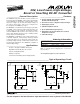
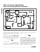
MAX629
MIN OFF-TIME
GENERATOR
TRIG
Q
S
LX
ISET
Q
F/F
GND
R
START-UP
MAX ON-TIME
GENERATOR
(10µs)
CONTROL
FB
REF
V
CC
1V
START-UP
COMPARATOR
ERROR
AMP
1.25V
REF
POL
TRIG
Q
SHDN
POLARITY
Figure 1. Functional Diagram