
Datasheet

MAX629
28V, Low-Power, High-Voltage,
Boost or Inverting DC-DC Converter
_______________________________________________________________________________________ 7
Setting the Current Limit
External current-limit selection provides added control
over the MAX629’s output performance. A higher cur-
rent limit increases the amount of energy stored in the
inductor during each cycle, which provides a higher
output current capability. For higher output current
applications, choose the 500mA current-limit option by
connecting ISET to V
CC
. When lower output current is
required, the 250mA current limit can provide several
advantages. First, a smaller inductor can be used,
which saves board area and cost. Second, the smaller
energy transfer per cycle reduces output ripple for a
given capacitor, providing design flexibility between
board area, cost, and output ripple by allowing cheap-
er, higher-ESR capacitors. Connect ISET to GND to
select the 250mA current-limit option.
Inductor Selection
The MAX629’s high switching frequency allows for the
use of a small inductor. The 47µH inductor shown in the
Typical Operating Circuit
is recommended for most
applications. Larger inductances reduce the peak
inductor current, but may limit output current capability
at low input voltages and provide slower start-up times.
Smaller inductances require less board space, but may
cause greater peak current due to current-sense com-
parator propagation delay. If input voltages below 2V
will be common, reducing the inductance to 22µH
might improve performance; however, maximum load
current and efficiency may decline. It is important to
thoroughly test operation under all input and output
conditions to ensure proper component selection.
Inductors with a ferrite core or equivalent are recom-
mended; powder iron cores are not recommended for
use with high switching frequencies. The inductor’s
incremental saturation rating must exceed the selected
current limit. For highest efficiency, use an inductor with
a low DC resistance (under 100mΩ). See Table 1 for a
list of inductor suppliers.
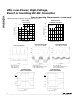
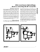
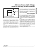
Figure 3. -20V for a Negative LCD Bias
* FOR SINGLE-SUPPLY OPERATION
MAX629
SHDN
C1
10µF
35V
C3
0.1µF
L1
47µH
R1
576k
1%
R2
35.7k
1%
D1
D1 = D2 = MBR0540L
D2
R3
2Ω
C5
2.2µF
C2
10µF
35V
CF
150pF
C4
0.1µF
V
CC
+2.7V
TO +5.5V
V
IN
+0.8V
TO +15V
V
OUT
-20V
LX
V
CC
GND
FB
REF
POL
ISET
*
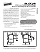
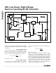
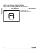
Figure 2. +24V for a Positive LCD Bias
MAX629
SHDN
V
OUT
+24V
V
CC
+2.7V
TO +5.5V
V
IN
+0.8V
TO +24V
* FOR SINGLE-SUPPLY OPERATION
*
C3
0.1µF
C4
0.1µF
C1
10µF
35V
C2
10µF
35V
C
F
150pF
R1
576k
1%
R2
31.6k
1%
L1
47µH
D1
MBR0540L
LX
V
CC
GND
FB
ISET
REF
POL
*FOR SINGLE-SUPPLY OPERATION *FOR SINGLE-SUPPLY OPERATION