
Datasheet
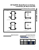

MAX6381–MAX6390
SC70/µDFN, Single/Dual Low-Voltage,
Low-Power µP Reset Circuits
6
Detailed Description
RESET Output
A µP reset input starts the µP in a known state. These
µP supervisory circuits assert reset to prevent code
execution errors during power-up, power-down, or
brownout conditions.
Reset asserts when V
CC
is below the reset threshold;
once V
CC
exceeds the reset threshold, an internal timer
keeps the reset output asserted for the reset timeout
period. After this interval, reset output deasserts. Reset
output is guaranteed to be in the correct logic state for
V
CC
≥ 1V.
Manual Reset Input (MAX6384/
MAX6385/MAX6386/MAX6390)
Many µP-based products require manual reset capabil-
ity, allowing the operator, a test technician, or external
logic circuitry to initiate a reset. A logic low on MR
asserts reset. Reset remains asserted while MR is low,
and for the reset active timeout period (t
RP
) after MR
returns high. This input has an internal 63kΩ pullup
resistor (1.56kΩ for MAX6390), so it can be left uncon-
nected if it is not used. MR can be driven with TTL or
CMOS logic levels, or with open-drain/collector outputs.
Connect a normally open momentary switch from MR to
GND to create a manual-reset function; external
debounce circuitry is not required. If MR is driven from
long cables or if the device is used in a noisy environ-
ment, connecting a 0.1µF capacitor from MR to GND
provides additional noise immunity.
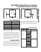
RESET IN Comparator
(MAX6387/MAX6388/MAX6389)
RESET IN is compared to an internal +1.27V reference.
If the voltage at RESET IN is less than 1.27V, reset
asserts. Use the RESET IN comparator as a user-
adjustable reset detector or as a secondary power-sup-
ply monitor by implementing a resistor-divider at RESET
IN (shown in Figure 1). Reset asserts when either V
CC
or RESET IN falls below its respective threshold volt-
age. Use the following equation to set the threshold:
V
INTH
= V
THRST
(R1/R2 + 1)
where V
THRST
= +1.27V. To simplify the resistor selec-
tion, choose a value of R2 and calculate R1:
R1 = R2 [(V
INTH
/V
THRST
) - 1]
Since the input current at RESET IN is 50nA (max),
large values can be used for R2 with no significant loss
in accuracy.
___________Applications Information
Negative-Going V
CC
Transients
In addition to issuing a reset to the µP during power-up,
power-down, and brownout conditions, the
MAX6381–MAX6390 are relatively immune to short dura-
tion negative-going V
CC
transients (glitches).
The
Typical Operating Characteristics
section shows the
Maximum Transient Durations vs. Reset Comparator
Overdrive, for which the MAX6381–MAX6390 do not
generate a reset pulse. This graph was generated using
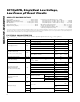
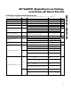
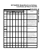
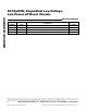
Reset Thresholds (-40°C to +125°C)
SUFFIX V
TH
(min) V
TH
(nom) V
TH
(max)
46 4.51 4.63 4.74
45 4.39 4.50 4.61
44 4.27 4.38 4.48
43 4.19 4.30 4.41
42 4.10 4.20 4.31
41 4.00 4.10 4.20
40 3.90 4.00 4.10
39 3.80 3.90 4.00
38 3.71 3.80 3.90
37 3.61 3.70 3.79
36 3.51 3.60 3.69
35 3.41 3.50 3.59
34 3.32 3.40 3.49
33 3.22 3.30 3.38
32 3.12 3.20 3.28
31 3.00 3.08 3.15
30 2.93 3.00 3.08
29 2.85 2.93 3.00
28 2.73 2.80 2.87
27 2.63 2.70 2.77
26 2.56 2.63 2.69
25 2.44 2.50 2.56
24 2.34 2.40 2.46
23 2.26 2.31 2.37
22 2.13 2.19 2.24
21 2.05 2.10 2.15
20 1.95 2.00 2.05
19 1.85 1.90 1.95
18 1.76 1.80 1.85
17 1.62 1.67 1.71
16 1.54 1.58 1.61