
Datasheet


Low-Power, Single/Dual-Voltage µP Reset Circuits
with Capacitor-Adjustable Reset Timeout Delay
MAX6412–MAX6420
7
Maxim Integrated
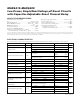
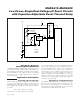
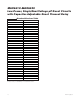
Dual-Voltage Monitoring
(MAX6418/MAX6419/MAX6420)
The MAX6418/MAX6419/MAX6420 contain both facto-
ry-trimmed threshold voltages and an adjustable reset
threshold input, allowing the monitoring of two voltages,
V
CC
and V
MON_TH
(see Figure 4). Reset is asserted
when either of the voltages falls below its respective
threshold voltage.
Application Information
Selecting a Reset Capacitor
The reset timeout period is adjustable to accommodate
a variety of µP applications. Adjust the reset timeout
period (t
RP
) by connecting a capacitor (C
SRT
) between
SRT and ground. Calculate the reset timeout capacitor
as follows:
C
SRT
= (t
RP
- 275µs) / (2.71 10
6
)
where t
RP
is in seconds and C
SRT
is in Farads
The reset delay time is set by a current/capacitor-con-
trolled ramp compared to an internal 0.65V reference.
An internal 240nA ramp current source charges the
external capacitor. The charge to the capacitor is
cleared when a reset condition is detected. Once the
reset condition is removed, the voltage on the capacitor
ramps according to the formula: dV/dt = I/C. The C
SRT
capacitor must ramp to 0.65V to deassert the reset.
C
SRT
must be a low-leakage (<10nA) type capacitor,
ceramic is recommended.
Operating as a Voltage Detector
The MAX6412–MAX6420 can be operated in a voltage
detector mode by leaving SRT unconnected. The reset
delay times for V
CC
rising above or falling below the
threshold are not significantly different. The reset output
is deasserted smoothly without false pulses.
RESET
CIRCUITRY
LASER-TRIMMED
RESISTORS
V
CC
V
CC
1.26V
RESET IN
GND
R1
R2
SRT
C
SRT
(RESET)
RESET
V
MON_TH
MAX6418
MAX6419
MAX6420
MAX6420
ONLY
R
L
μP
Figure 4. MAX6418/MAX6419/MAX6420 Monitoring Two Voltages