
Datasheet


MAX6495–MAX6499
72V, Overvoltage-Protection Switches/
Limiter Controllers with an External MOSFET
6
Maxim Integrated
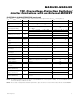
Pin Description
PIN
MAX6495
MAX6496
MAX6497/MAX6498
MAX6499
NAME FUNCTION
1111 IN
Positive Supply Voltage. Connect IN to the positive side of the input voltage. Bypass IN
with a 10µF capacitor to GND.
2222SHDN
Shutdown Input. Drive SHDN low to force GATE low and turn off the external n-channel
MOSFET. Drive SHDN low and then high to reset the overvoltage-condition latch. SHDN
is internally pulled to GND with 1µA of current. Connect SHDN to IN for normal operation.
3333
OVSET
Overvoltage-Threshold Adjustment Input. Connect OVSET to an external resistive
voltage-divider network to adjust the desired overvoltage-disable or overvoltage-limit
threshold. Connect the resistor network to the input side (drain) of the n-channel
MOSFET for overvoltage switch turn-off applications or to the output side (source) of the
n-channel MOSFET for overvoltage-limiting applications (MAX6495/MAX6496/MAX6499).
4 5 5 5 GND Ground
5 6 6 6 GATE
Gate-Driver Output. Connect GATE to the gate of the external n-channel MOSFET switch.
GATE is the output of a charge pump with a 100µA pullup current to 10V (typ) above IN
during normal operation. GATE is quickly clamped to OUTFB during an overvoltage
condition. GATE pulls low when SHDN is low.
6777
OUTFB
Output-Voltage-Sense Input. Connect OUTFB to the source of the external n-channel
MOSFET switch.
—
4
— — GATEP
p-Channel Gate-Driver Output. Connect GATEP to the gate of an external p-channel
MOSFET to provide low-drop reverse-voltage protection. GATEP is biased to ensure that
the p-channel MOSFET is on during normal operating modes, the gate-to-source is not
overstressed during load-dump/overvoltage conditions, and the p-channel MOSFET is
off during reverse-battery conditions.
—
8
——
N.C. No Connection. Not internally connected.
—
—
4
—
POK
Power-OK Output. POK is an open-drain output. POK remains low while POKSET is
below the internal POKSET threshold. POK goes high impedance when POKSET goes
above the internal POKSET threshold. Connect POK to an external pullup resistor.
—
—
8
— POKSET
Power-OK Threshold-Adjustment Input. POK remains low while POKSET is below the
internal POKSET threshold (1.18V). POK goes high impedance when POKSET goes
above the internal POKSET threshold (1.24V). Connect a resistive divider from OUTFB
to POKSET to adjust the desired undervoltage threshold.
—
——
4
CLEAR
Latch Clear Input. Connect CLEAR to a logic-high to latch the device off after an
overvoltage condition. With OVSET below V
TH
, pulse CLEAR low (5µs typ)
to reset the output latch. Connect CLEAR to GND to make the latch transparent.
—
——
8
UVSET
Undervoltage-Threshold Adjustment Input. Connect UVSET to an external resistive
voltage-divider network to adjust the desired undervoltage threshold.
—
———
EP
Exposed Pad. EP is internally connected to GND. Connect EP to the ground plane to
provide a low thermal-resistance path from the IC junction to the PC board. Do not use
as the primary electrical connection to GND.