
Datasheet


MAX6495–MAX6499
72V, Overvoltage-Protection Switches/
Limiter Controllers with an External MOSFET
8
Maxim Integrated
The gate cycles during overvoltage-limit and overvolt-
age-switch modes are quite similar but have distinct
characteristics. In overvoltage-switch mode, GATE is
enhanced to (V
IN
+ 10V) while the monitored V
IN
volt-
age remains below the overvoltage fault threshold
(OVSET < V
TH+
). When an overvoltage fault occurs
(OVSET ≥ V
TH+
), GATE is pulled one diode drop below
OUTFB, turning off the external MOSFET and discon-
necting the load from the input. GATE remains low
(MOSFET off) as long as the V
IN
voltage is above the
overvoltage fault threshold. As V
IN
falls back below the
overvoltage fault threshold, GATE is again enhanced to
(V
IN
+ 10V).
In overvoltage-limit mode, GATE is enhanced to (V
IN
+10V) while the monitored OUTFB voltage remains
below the overvoltage fault threshold (OVSET < V
TH+
).
When an overvoltage fault occurs (OVSET ≥ V
TH+
),
GATE is pulled one diode drop below OUTFB until
OUTFB drops 5% below the overvoltage fault threshold
(MAX6495/MAX6496/MAX6499). GATE is then turned
back on until OUTFB reaches the overvoltage fault
threshold and GATE is again turned off. GATE cycles in
a sawtooth waveform until OUTFB remains below the
overvoltage fault threshold and GATE remains con-
stantly on (V
IN
+10V). The overvoltage limiter’s saw-
tooth GATE output operates the MOSFET in a
switched-linear mode while the input voltage remains
above the overvoltage fault threshold. The sawtooth fre-
quency depends on the load capacitance, load current,
and MOSFET turn-on time (GATE charge current and
GATE capacitance).
GATE goes high when the following startup conditions
are met: V
IN
is above the UVLO threshold, SHDN is
high, an overvoltage fault is not present, and the device
is not in thermal shutdown.
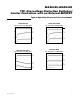
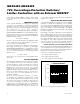
Undervoltage Monitoring (MAX6499)
The MAX6499 includes undervoltage and overvoltage
comparators for window detection (see Figures 3 and
12). GATE is enhanced and the n-channel MOSFET is
on when the monitored voltage is within the selected
“window.” When the monitored voltage falls below the
lower limit (V
TRIPLOW
) or exceeds the upper limit
(V
TRIPHIGH
) of the window, GATE falls to OUTFB turn-
ing off the MOSFET. The application in Figure 3 shows
the MAX6499 enabling the DC-DC converter when the
monitored voltage is in the selected window.
The resistor values R1, R2, and R3 can be calculated
as follows:
where R
TOTAL
= R1 + R2 + R3.
Use the following steps to determine the values for R1,
R2, and R3:
1) Choose a value for R
TOTAL
, the sum of R1, R2, and
R3. Because the MAX6499 has very high input
impedance, R
TOTAL
can be up to 5MΩ.
2) Calculate R3 based on R
TOTAL
and the desired
upper trip point:
3) Calculate R2 based on R
TOTAL
, R3, and the desired
lower trip point:
4) Calculate R1 based on R
TOTAL
, R2, and R3:
R1 = R
TOTAL
– R2 – R3
To improve ESD protection, keep R3 ≥ 1kΩ.
R
VR
V
R
TH TOTAL
TRIPLOW
23
=
()
×
⎡
⎣
⎢
⎢
⎤
⎦
⎥
⎥
−
−
R
VR
V
TH TOTAL
TRIPHIGH
3
=
×
+
VV
R
RR
VV
R
R
TRIPLOW TH
TOTAL
TRIPHIGH TH
TOTAL
=
()
+
⎛
⎝
⎜
⎞
⎠
⎟
=
()
⎛
⎝
⎜
⎞
⎠
⎟
−
+
23
3
OVSET
GND
CLEAR
GATE OUTFB
IN
SHDN
UVSET
R2
V
IN
R3
R1
MAX6499
DC-DC
CONVERTER
GND
IN OUT
Figure 3. MAX6499 Window-Detector Circuit