
Datasheet


MAX6495–MAX6499
72V, Overvoltage-Protection Switches/
Limiter Controllers with an External MOSFET
9
Maxim Integrated
Power-OK Output (MAX6497/MAX6498)
POK is an open-drain output that remains low when the
voltage at POKSET is below the internal POKSET
threshold (1.18V). POK goes high impedance when
POKSET goes above the internal POKSET threshold
(1.24V). Connect a resistive divider from OUTFB to
POKSET to adjust the desired undervoltage threshold.
Use a resistor in the 100kΩ range from POKSET to
GND to minimize current consumption.
Overvoltage Latch Function
The MAX6497/MAX6499 offers a latch function that pre-
vents the external MOSFET from turning on until the
latch is cleared. For the MAX6497, the latch can be
cleared by cycling the power on the input IN to a volt-
age below the undervoltage lockout or by pulling the
shutdown input low and then back to a logic-high
state. The MAX6499 offers a CLEAR input that latches
the n-MOSFET off when CLEAR is high. The latch is
removed when the CLEAR input is plused low. Connect
CLEAR low to make the latch transparent.
Overvoltage Retry Function
The MAX6498 offers an automatic retry function that
tries to enhance the external n-channel MOSFET after
the overvoltage condition is removed. When the monitored
input voltage detects an overvoltage condition (V
SET
>
V
TH+
), the n-MOSFET is turned off. The MOSFET stays off
until the voltage at V
SET
falls below its V
TH-
(typically
0.13V), at which point the output tries to turn on again.
Applications Information
Load Dump
Most automotive applications run off a multicell “12V”
lead-acid battery with a nominal voltage that swings
between 9V and 16V (depending on load current,
charging status, temperature, battery age, etc.). The
battery voltage is distributed throughout the automobile
and is locally regulated down to voltages required by
the different system modules. Load dump occurs when
the alternator is charging the battery and the battery
becomes disconnected. The alternator voltage regula-
tor is temporarily driven out of control. Power from the
alternator flows into the distributed power system and
elevates the voltage seen at each module. The voltage
spikes have rise times typically greater than 5ms and
decays within several hundred milliseconds but can
extend out to 1s or more depending on the characteris-
tics of the charging system. These transients are capa-
ble of destroying sensitive electronic equipment on the
first “fault event.”
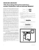
Setting Overvoltage Thresholds
OVSET provides an accurate means to set the overvolt-
age level for the MAX6495–MAX6499. Use a resistive
divider to set the desired overvoltage condition (see
Figure 2). OVSET has a rising 1.24V threshold with a
5% falling hysteresis (MAX6495/MAX6496/MAX6499)
and a rising 0.505V threshold with a falling 0.15V
threshold (MAX6497/MAX6498).
Begin by selecting the total end-to-end resistance, R
TO-
TAL
= R1 + R2. Choose R
TOTAL
to yield a total current
equivalent to a minimum 100 x I
SET
(OVSET’s input bias
current) at the desired overvoltage threshold.
For example:
With an overvoltage threshold (V
OV
) set to 20V for the
MAX6495/MAX6496/MAX6499, R
TOTAL
< 20V / (100 x
I
SET
), where I
SET
is OVSET’s 50nA (max) input bias current.
R
TOTAL
< 4MΩ
Use the following formula to calculate R2:
where V
TH+
is the 1.24V OVSET rising threshold and
V
OV
is the desired overvoltage threshold.
R2 = 248kΩ. Use a 249kΩ standard resistor.
R
TOTAL
= R2 + R1, where R1 = 3.751MΩ. Use a
3.74MΩ standard resistor.
A lower value for total resistance dissipates more power
but provides slightly better accuracy. To improve ESD
protection, keep R2 ≥ 1kΩ.
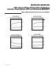
Reverse-Battery Protection
The MAX6496 is an overvoltage-protection circuit that is
capable of driving a p-channel MOSFET to prevent
reverse-battery conditions. This MOSFET eliminates the
need for external diodes, thus minimizing the input volt-
age drop (see Figure 8).
Inrush/Slew-Rate Control
Inrush current control can be implemented by placing a
capacitor from GATE to GND to slowly ramp up the
GATE, thus limiting the inrush current and controlling
GATE’s slew rate during initial turn-on. The inrush cur-
rent can be approximated using the following equation:
I
C
C
II
INRUSH
OUT
GATE
GATE LOAD
=×+
RV
R
V
TH
TOTAL
OV
2 =×
+