
Datasheet
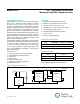


Time-Select Pins (TS1, TS0)
Table 1 shows the configuration of the Time-select pins
for the MAX6575L/H. Each device allows four selectable
timeout multipliers intended to prevent overlapping when
multiple devices are used on the same I/O line. Tie TS1
and TS0 to either GND or V
DD
to select the desired tem-
perature multiplier.
To monitor several chips on the same I/O line, different
timeout multipliers should be selected using the TS1 and
TS0 pins. The timeout periods are then scaled so that the
response times will not overlap (see Timeout Selection).
Applications Information
Timeout Selection
Under extreme temperature conditions, it is possible for
an overlap to occur between the timeout delays of differ-
ent sensors in a multidrop configuration. This overlap can
occur only if the temperature differential recorded between
two devices is very large. Timeout overlaps can be avoid-
ed in multidrop configurations by selecting the appropriate
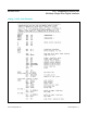
timeout multipliers. Table 2 illustrates the allowable tem-
perature differential between devices when the maximum
error is present on each device. Allowable temperature
differentials greater than 165°C indicate no overlap.
For example, if the maximum temperature differential
in a system is 80°C, the only combinations of timeout
multipliers that could result in timeout overlap would be a
320:480μs/°K (70.2°C) or a 480:640μs/°K (37.9°C) com-
bination. As long as these combinations of timeout mul-
tipliers are not used in the same multidrop configuration,
no overlap can occur. Thus, seven MAX6575L/H parts
can be used in the same multidrop configuration if the
maximum temperature differential between parts is 80°C.
A similar analysis shows that four MAX6575L/H parts
can be used when the maximum temperature differential
extends over the entire 165°C range of the part.
Noise Considerations
The accuracy of the MAX6575L/H timeout delay is sus-
ceptible to noise generated both internally and externally.
The effects of external noise can be minimized by placing
a 0.1μF ceramic bypass capacitor close to the device’s
supply pin. Internal noise is inherent in the operation of
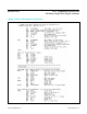
the device and is detailed in Table 3. Internal averag-
ing minimizes the effect of this noise when using longer
timeout multipliers. The effects of this noise are included
in the overall accuracy of the device as specified in the
Electrical Characteristics table.
Table 2. Allowable Temperature Differential (°C)
Table 3. Typical Peak Noise Amplitude
TIMEOUT
MULTIPLIER
MAX6575L MAX6575H
5 20 40 80 160 320 480 640
5 >165 >165 >165 >165 >165 >165 >165
20 95.5 >165 >165 >165 >165 >165
40 132.0 >165 >165 >165 >165
80 153.5 >165 >165 >165
160 >165 >165 >165
320 70.2 >165
480 37.9
640
PARAMETER MAX6575L MAX6575H
Timeout
Multiplier
5 20 40 80 160 320 480 640
Noise
Amplitude
(°C)
±0.33 ±0.15 ±0.15
±0.098 ±0.091 ±0.063 ±0.043 ±0.037
MAX6575L/H SOT Temperature Sensor with
Multidrop Single-Wire Digital Interface
www.maximintegrated.com
Maxim Integrated
│
5