
Datasheet


Applications Information
Quick-Look Circuits
Figure 3 shows a quick-look application circuit for the
MAX6576 using a universal counter measuring period.
TS1 and TS0 are both tied to ground to select a scalar
multiplier of 10μs/°K. The MAX6576 converts the ambi-
ent temperature into a square wave with a period that is
10 times the absolute temperature of the device in μs.
At room temperature, the universal counter will display
approximately 2980μs.
Figure 4 shows a quick-look application circuit for the
MAX6577 using a universal counter measuring frequency.
TS1 is tied to ground and TS0 is tied to V
DD
to select a
scalar multiplier of 1Hz/°K. The MAX6577 converts the
ambient temperature into a square wave with a frequency
that is equal to the absolute temperature of the device
in Hertz. At room temperature, the universal counter will
display approximately 298Hz.
Interfacing with a Microcontroller
Figure 5 shows the MAX6577 interfaced with an 8051 μC.
In this example, TS1 is tied to ground and TS0 is tied to
V
DD
to select a scalar multiplier of 1Hz/°K. The MAX6577
converts the ambient temperature into a square wave with
a frequency that is equal to the absolute temperature of
the device in Hertz. The 8051 μC reads the frequency of
the square-wave output of the MAX6577 into Timer 0 and
displays the temperature as degrees Celsius in binary on
Port 1. Listing 1 provides the code for this application. The
interface is similar for the MAX6576, except the μC will
perform a period measurement.
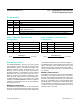
Noise Considerations
The accuracy of the MAX6576/MAX6577 is susceptible to
noise generated both internally and externally. The effects
of external noise can be minimized by placing a 0.1μF
ceramic bypass capacitor close to the supply pin of the
devices. Internal noise is inherent in the operation of the
devices and is detailed in Table 3. Internal averaging mini-
mizes the effect of this noise when using longer scalar
timeout multipliers. The effects of this noise are included
in the overall accuracy of the devices as specified in the
Electrical Characteristics.
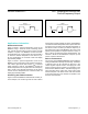
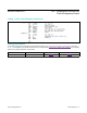
Figure 1. MAX6576 Timing Diagram Figure 2. MAX6577 Timing Diagram
t
OUT
MAX6576
CLOCK WAVEFORM OUTPUT
t
OUT
MAX6577
CLOCK WAVEFORM OUTPUT
f
OUT
= 1 / t
OUT
f
OUT
(°K)
MAX6576/MAX6577 SOT Temperature Sensors with
Period/Frequency Output
www.maximintegrated.com
Maxim Integrated
│
5