
Datasheet
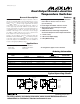

MAX6685/MAX6686
Detailed Description
The MAX6685/MAX6686 dual-output remote-sensing
junction temperature switches incorporate a precision
remote-junction temperature sensor and two compara-
tors. These devices use an external P-N junction as the
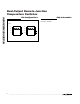
temperature-sensing element (see Typical Operating
Circuits).
The MAX6685/MAX6686 provide noise immunity by
integration and oversampling of the diode voltage, but
good design practice includes routing the DXP and
DXN lines away from noise sources, such as high-
speed digital lines, switching regulators, inductors, and
transformers. The DXP and DXN traces should be
paired together and surrounded by a ground plane
whenever possible.
The 5°C hysteresis keeps the outputs from “chattering”
when the measured temperature is close to the threshold
temperature. The MAX6685/MAX6686 are available with
preset upper temperature thresholds of +120°C or
+125°C. The lower temperature thresholds are pin pro-
grammable in 5°C increments (Table 1). Two tempera-
ture ranges are available for the lower trip threshold:
+40°C to +80°C and +75°C to +115°C. S1 and S2 pins
must be set to the desired trip temperature before power
is applied to the V
DD
pin. If this is done after the power is
turned on, the lower trip threshold remains set to the
point where S1 and S2 were when power was applied.
Applications Information
Remote-Diode Selection
The MAX6685/MAX6686 are optimized to measure the
die temperature of CPUs and other ICs that have on-chip
temperature-sensing diodes. These on-chip diodes are
substrate PNPs with their collectors grounded. Connect
the base of the PNP to DXN and the emitter to DXP. When
using a discrete, diode-connected NPN or PNP as a
sensing diode, use a good-quality small-signal device.
Examples are listed in Table 2. Tight specifications for for-
ward current gain indicate the manufacturer has good
process controls and that the devices have consistent
V
be
characteristics. Always use a transistor for the sens-
ing junction; diodes do not work.
Dual-Output Remote-Junction
Temperature Switches
4 _______________________________________________________________________________________
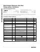
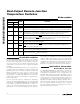
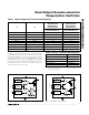
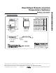
Pin Description
PIN
MAX6685 MAX6686
NAME FUNCTION
11V
DD
Power-Supply Input. Bypass to GND with a 0.1µF capacitor.
2 2 GND Ground
3 3 DXP
This pin connects to the positive (anode) terminal of the external P-N sense junction. It sources
current into the external junction. A 2200pF capacitor should be connected across DXP and DXN.
4 4 DXN
This pin connects to the negative (cathode) terminal of the external P-N sense junction. It sinks
current from the external junction. A 2200pF capacitor should be connected across DXP and
DXN. DXN must be connected to the GND pin with the shortest possible connection.
55T
HIGH
Open-Drain, Active-Low Output. T
HIGH
goes low when the temperature exceeds the factory-
programmed upper temperature threshold, either +120°C or +125°C. Connect a pullup resistor
(typically 10kΩ) between T
HIGH
and a positive supply up to 5.5V.
6—T
LOW
CMOS Push-Pull, Active-High Output. T
LOW
goes HIGH when the temperature exceeds the pin-
programmed lower temperature threshold.
—6T
LOW
Open-Drain, Active-Low Output. T
LOW
goes LOW when the temperature exceeds the pin-
programmed lower temperature threshold. Connect a pullup resistor (typically 10kΩ) between
T
LOW
and a positive supply up to 5.5V.
77S1
Threshold Select Input. Used in conjunction with S2 to set the lower threshold for T
LOW
(Table 1).
It can be connected to V
DD
, GND, or left floating.
88S2
Threshold Select Input. Used in conjunction with S1 to set the lower threshold for T
LOW
(Table 1).
It can be connected to V
DD
, GND, or left floating.