
Datasheet

Standard- vs. A-Version Comparison
The MAX6701/MAX6702/MAX6703/MAX6705/MAX6706/
MAX6707s’ WDO latches low when one of the following
events occurs:
● The watchdog timer times out (1.6s, typ).
● V
CC
, RST_IN1, or RST_IN2 is below its reset
threshold.
● MR is pulled low.
● WDO only deasserts with a valid WDI transition.
The MAX6701(A)/MAX6702(A)/MAX6703(A)/MAX6705(A)/
MAX6706(A)/ MAX6707(A)s’ WDO asserts when either
V
CC
, RST_IN1, or RST_IN2 is below its reset thresh-
old. WDO deasserts without a timeout delay when the
undervoltage situation has expired. WDO is latched low
when the watchdog timer elapses without seeing a WDI
transition. WDO deasserts with a valid WDI transition
OR by pulling MR low.
See Figures 4 and 5 for standard-version timing. See
Figures 6 and 7 for A-version timing.
Watchdog Timer
The MAX6701–MAX6707 watchdog circuit monitors the
µP’s activity. If the µP does not toggle the WDI within 1.6s,
WDO goes low. When RESET is asserted, the watchdog
timer stays cleared and does not count. As soon as reset
is released, the timer starts counting. WDO deasserts
after a valid transition is detected at WDI. Pulses as short
as 50ns can be detected.
Typically, WDO is connected to the NMI input of a µP.
When V
CC
, RST_IN1, or RST_IN2 drop below the reset
threshold, WDO goes low whether or not the watchdog
timer has timed out. Normally this would trigger an NMI,
but RESET goes low simultaneously, and thus overrides
the NMI.
The MAX6704 watchdog circuit does not have an inde-
pendent watchdog output (WDO). If the µP does not
toggle the watchdog input within 1.6s, the MAX6704
asserts a reset output pulse for the reset timeout period.
Manual Reset
The manual reset input (MR) allows reset to be
triggered by a pushbutton switch. The switch is
effectively debounced by the reset pulse width. MR is
CMOS logic compatible, so it can be driven by an external
logic line. MR can be used to force a watchdog timeout to
generate a reset pulse in the MAX6701(A)/MAX6702(A)/
MAX6703(A)/MAX6705(A)/MAX6706(A)/MAX6707(A) by
connecting WDO to MR.
Power-Fail Comparator
The uncommitted power-fail comparator can be used
for various purposes because its noninverting input and
output are externally available. The inverting input is
internally connected to a 0.62V reference. To build an
early warning circuit for power failure, connect the PFI
pin to a voltage-divider (see the Typical Operating
Circuit). Choose the voltage-divider ratio so that the
voltage at PFI falls below 0.62V just before the regulator
drops out. Use PFO to interrupt the µP so it can prepare
for an orderly power-down. The low-input current at this
pin allows for large resistor values in the divider.
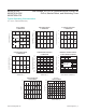
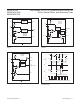
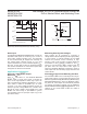
Figure 6. MAX6701(A)/MAX6702(A)/MAX6703(A)/
MAX6705(A)/ MAX6706(A)/MAX6707(A) RESET, MR, and
WDO Timing with WDI Three-Stated
Figure 5. MAX6701/MAX6702/MAX6703/MAX6705/MAX6706/
MAX6707 Watchdog
t
RP
t
RP
+5V
0V
RESET
WDO
+5V
0V
MR
t
MR
+5V
0V
V
CC
V
TH
V
TH
t
MD
t
WD
t
WD
+5V
0V
WDI
+5V
0V
WDO
+5V
0V
RESET
+5V
0V
(RESET)
t
RP
RESET EXTERNALLY
TRIGGERED BY MR
+5V
0V
MR
( ) ARE FOR MAX6702/MAX6706 ONLY.
t
WDI
www.maximintegrated.com
Maxim Integrated
│
8
MAX6701-08/
MAX6701A-03A/
MAX6705A-07A
Low-Voltage, SOT23 µP Supervisors with Power-Fail
In/Out, Manual Reset, and Watchdog Timer