
Datasheet

Reset Input
The MAX6701(A)/MAX6702(A)/MAX6703(A) include two
adjustable reset inputs for monitoring up to a total of
three system voltages (including V
CC
). The thresholds
for the monitored RST_IN supplies are externally set
with resistor-divider networks (Figure 8). The reset
output is asserted if any of the monitored supplies (V
CC
,
RST_IN1, or RST_IN2) go below its specified threshold
and remains asserted for the reset timeout period after
all supplies are above their thresholds.
Applications Information
Ensuring a Valid RESET Output
Down to V
CC
= 0
When V
CC
falls below 1V, the MAX6701–MAX6708
RESET output no longer sinks current; it becomes an
open circuit. High-impedance CMOS logic inputs can
drift to undetermined voltages if left undriven. If a pull-
down resistor is added to the RESET pin, as shown
in Figure 9, any stray charge or leakage currents are
drained to ground, holding RESET low. A resistor value
(R1) is not critical; 100kΩ is large enough not to load
RESET and small enough to pull RESET to ground.
This application works for push-pull output only (not for
open-drain resets).
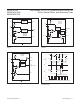
Monitoring Other System Voltages
Other systems can be monitored by connecting a
voltage-divider to PFI and adjusting the ratio appropriately.
In noisy systems, a capacitor between PFI and GND
reduces the power-fail circuit’s sensitivity to high-
frequency noise on the line being monitored. Reset can
be asserted on other voltages in addition to the V
CC
supply line. Connect PFO to MR to initiate a reset out-
put pulse when PFI drops below 0.62V. Figure 10
shows the MAX6704–MAX6708 configured to assert a
reset output when the secondary supply falls below the
reset threshold.
Generating a Reset from Watchdog Overow
Connect WDO to MR to force a watchdog timeout to gen-
erate a reset pulse for only the reset timeout period on the
MAX6701(A)/MAX6702(A)/MAX6703(A)/MAX6705(A)/
MAX6706(A)/MAX6707(A). When the MAX6704 watch-
dog times out, reset outputs are automatically asserted
(no external connections required). For the MAX6701/
MAX6702/MAX6703/MAX6705/MAX6706/MAX6707 non-A
versions, do not connect WDO to MR; this creates a
locked condition.
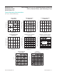
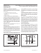
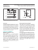
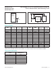
Figure 8. Calculating Adjustable Voltage ThresholdsFigure 7. MAX6701(A)/MAX6702(A)/MAX6703(A)/
MAX6705(A)/ MAX6706(A)/MAX6707(A) Watchdog Timing
R1
R2
0.62V
PFI, RST_IN1, OR RST_IN2
V
EXTERNAL
0.62
R1 = R2 x
(
V
EXT-TH
- 1
)
R2
V
EXT-TH
=
(
1 +
R1
)
x 0.62V
WHERE V
EXT-TH
IS THE EXTERNAL VOLTAGE TRIP LEVEL.
MAX6701(A)–
MAX6708
t
WD
t
WD
t
WD
+5V
0V
WDI
+5V
0V
WDO
+5V
0V
RESET
+5V
0V
(RESET)
t
RP
+5V
0V
MR
( ) ARE FOR MAX6702(A)/MAX6706(A) ONLY.
t
WDI
www.maximintegrated.com
Maxim Integrated
│
9
MAX6701-08/
MAX6701A-03A/
MAX6705A-07A
Low-Voltage, SOT23 µP Supervisors with Power-Fail
In/Out, Manual Reset, and Watchdog Timer