
Datasheet

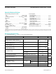


Terminal Voltage (with respect to GND)
V
CC
................................................................... -0.3V to +6.0V
V
BATT
...............................................................-0.3V to +6.0V
All Other Inputs (Note 1) ................... -0.3V to (V
OUT
+ 0.5V)
Input Current
V
CC
............................................................................... 200mA
V
BATT
.............................................................................50mA
GND ...............................................................................20mA
Output Current
V
OUT
.....................................................Short circuit protected
All Other Outputs ............................................................ 20mA
Rate-of-Rise, V
BATT
,
V
CC
..............................................100V/µs
Operating Temperature Range
C suffix ................................................................0°C to +70°C
E suffix ............................................................ -40°C to +85°C
M suffix ......................................................... -55°C to +125°C
Power Dissipation
8-Pin Plastic DIP
(derate 5mW/°C above +70°C) ....................................400mV
8-Pin CERDIP
(derate 8mW/°C above +85°C) ....................................500mV
16-Pin Plastic DIP
(derate 7mW/°C above +70°C) ....................................600mV
16-Pin Small Outline
(derate 7mW/°C above +70°C) ....................................600mV
16-Pin CERDIP
(derate 10mW/°C above +85°C) ..................................600mV
Storage Temperature Range ............................ -65°C to +160°C
Lead Temperature (Soldering, 10s) ................................... 300°C
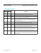
V
CC
= full operating range, V
BATT
= 2.8V, T
A
= +25°C, unless otherwise noted.)
PARAMETER CONDITIONS MIN TYP MAX UNITS
BATTERY BACKUP SWITCHING
Operating Voltage Range
(MAX690, MAX691, MAX694, MAX695 V
CC
)
4.75 5.5
V
Operating Voltage Range (MAX690, MAX691,
MAX694, MAX695 V
BATT
)
2.0 4.25
Operating Voltage Range
(MAX692, MAX693 V
CC
)
4.5 5.5
Operating Voltage Range
(MAX692, MAX693 V
BATT
)
2.0 4.0
V
OUT
Output Voltage
I
OUT
= 1mA
V
CC
-
0.3
V
CC
-
0.1
V
I
OUT
= 50mA
V
CC
-
0.5
V
CC
-
0.25
V
OUT
in Battery Backup Mode I
OUT
= 250µA, V
CC
< V
BATT
- 0.2V
V
BATT
- 0.1
V
BATT
- 0.02
V
Supply Current (Excluded I
OUT
)
I
OUT
= 1mA 2 5
mA
I
OUT
= 50mA 3.5 10
Supply Current in Battery Backup Mode V
CC
= 0V, V
BATT
= 2.8V 0.6 1 µA
Battery Standby Current
(+ = Discharge, - = Charge)
5.5V > V
CC
>
V
BATT
+ 1V
T
A
= +25°C -0.1 +0.02
µA
T
A
= full operating
range
-1.0 +0.02
Battery Switchover Threshold
(V
CC
- V
BATT
)
Power-up 70
mV
Power-down 50
MAX690–MAX695 Microprocessor Supervisory Circuits
www.maximintegrated.com
Maxim Integrated
│
2
Absolute Maximum Ratings
Stresses beyond those listed under “Absolute Maximum Ratings” may cause permanent damage to the device. These are stress ratings only, and functional operation of the device at these
or any other conditions beyond those indicated in the operational sections of the specifications is not implied. Exposure to absolute maximum rating conditions for extended periods may affect
device reliability.
Electrical Characteristics