
Datasheet

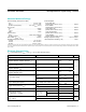


V
CC
= full operating range, V
BATT
= 2.8V, T
A
= +25°C, unless otherwise noted.)
Note 1: The input voltage limits on PFI and WDI may be exceeded provided the input current is limited to less than 10mA.
Note 2: WDI is guaranteed to be in the mid-level (inactive) state if WDI is floating and V
CC
is in the operating voltage range. WDI is
internally biased to 38% of V
CC
with an impedance of approximately 125kΩ.
PARAMETER CONDITIONS MIN TYP MAX UNITS
CHIP ENABLE GATING
CE IN Thresholds
V
IL
0.8
V
V
IH
3.0
CE IN Pullup Current 3 µA
CE OUT Output Voltage
I
SINK
= 3.2mA 0.4
VI
SOURCE
= 3.0mA V
OUT
- 1.5
I
SOURCE
= 1µA, V
CC
= 0V V
OUT
- 0.05
CE Propagation Delay V
CC
= 5V 50 200 ns
OSCILLATOR
OSC IN Input Current ±2 µA
OSC SEL Input Pullup Current 5 µA
OSC IN Frequency Range OSC SEL = 0V 0 250 kHz
OSC IN Frequency
with External Capacitor
OSC SEL = 0V
C
OSC
= 47pF
4 kHz
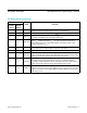
PIN
NAME FUNCTION
MAX690/
MAX692/
MAX694
MAX691/
MAX693/
MAX695
2 3 V
CC
The +5V Input
8 1 V
BATT
Backup Battery Input. Connect to Ground if a backup battery is not used.
1 2 V
OUT
The higher of V
CC
or V
BATT
is internally switched to V
OUT
. Connect V
OUT
to V
CC
if
V
OUT
and V
BATT
are not used. Connect a 0.1µF or larger bypass capacitor to V
OUT
.
3 4 GND 0V Ground Reference for All Signals
7 15 RESET
RESET goes low whenever V
CC
falls below either the reset voltage threshold or the
V
BATT
input voltage. The reset threshold is typically 4.65V for the MAX690/691/694/695,
and 4.4V for the MAX692 and MAX693. RESET remains low for 50ms after V
CC
returns
to 5V, (except 200ms in MAX694/695). RESET also goes low for 50ms if the Watchdog
Timer is enabled but not serviced within its timeout period. The RESET pulse width can
be adjusted as shown in Table 1.
6 11 WDI
Watchdog Input (WDI). WDI is a three level input. If WDI remains either high or low for
longer than the watchdog timeout period, RESET pulses low and WDO goes low. The
Watchdog Timer is disabled when WDI is left oating or is driven to mid-supply. The
timer resets with each transition at the Watchdog Timer input.
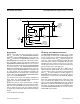
4 9 PFI
Noninverting Input to the Power-Fail Comparator. When PFI is less than 1.3V, PFO
goes low. Connect PFI to GND or V
OUT
when not used. See Figure 1.
MAX690–MAX695 Microprocessor Supervisory Circuits
www.maximintegrated.com
Maxim Integrated
│
4
Electrical Characteristics (continued)
Pin Description