
Datasheet

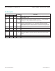
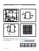

Figure 4 shows the RESET output of the MAX700/
MAX701/MAX702 in the correct state for V
CC
voltages
down to 0V. Note the effect of the built-in hysteresis on
the trigger lever of RESET.
Figure 1. MAX700 Block Diagram
Figure 3. MAX700 Connected for External Senses and
Hysteresis
Figure 2. MAX700 Typical Connection Diagram
Figure 4. Typical MAX700/MAX701/MAX702 RESET Output vs.
V
CC
PACKAGE
TYPE
PACKAGE
CODE
OUTLINE
NO.
LAND
PATTERN NO.
8 PDIP P8+2 21-0143 —
8 Narrow SO S8+4 21-0041 90-0096
RESET
1M
1.29VREF
OSC
RC
R
R
COMPARATOR
RESET
GND
1
2
8
7
V
CC
CTL
SENSE
HYST
150k
MR
3
4
6
5
MAX700
GND
1
2
8
7
SENSE
MANUAL
RESET
BUTTON
HYST
MR
3
4
6
N.C.
R1
R3R2
V
IN
TO µP
V
IN
3V TO 15V
V
L
= LOWER VOLTAGE THRESHOLDR1 = R2
(
V
L
- 1
)
1.29
R3 =
V
T
R1
V
U
- V
L
V
U
= UPPER VOLTAGE THRESHOLD
HYSTERESIS = V
U
- V
L
5
MAX700
RESET
RESET
V
CC
CTL
GND
1
2
8
7
SENSE
MANUAL
RESET
BUTTON
HYST
MR
3
4
6
N.C.
N.C.
TO µP
+5V
5
MAX700
RESET
RESET
V
CC
CTL
RESET
0V
0V
2V/div
2V/div
1s/div
V
CC
MAX700/MAX701/MAX702 Power-Supply Monitor with Reset
www.maximintegrated.com
Maxim Integrated
│
5
Package Information
For the latest package outline information and land patterns
(footprints), go to www.maximintegrated.com/packages. Note
that a “+”, “#”, or “-” in the package code indicates RoHS status
only. Package drawings may show a different suffix character, but
the drawing pertains to the package regardless of RoHS status.