
Datasheet


MAX823/MAX824/MAX825
5-Pin Microprocessor Supervisory Circuits With
Watchdog Timer and Manual Reset
4 _______________________________________________________________________________________
Note 1: Over-temperature limits are guaranteed by design and not production tested.
Note 2: The RESET short-circuit current is the maximum pullup current when RESET is driven low by a µP bidirectional reset pin.
Note 3: WDI is internally serviced within the watchdog period if WDI is left unconnected.
Note 4: The WDI input current is specified as the average input current when the WDI input is driven high or low. The WDI input is
designed to drive a three-stated output device with a 10µA maximum leakage current and a maximum capacitive load of
200pF. This output device must be able to source and sink at least 200µA when active.
PARAMETER
SYMBOL
CONDITIONS
MIN
TYP
MAX
U N IT S
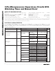
MANUAL RESET INPUT (MAX823/MAX825)
V
IL
0.3
✕
V
CC
MR Input Voltage
V
IH
0.7
✕
V
CC
V
MR Pulse Width 1.0 µs
MR Noise Immunity (pulse width
with no reset)
100
ns
MR to Reset Delay
500
ns
MR Pullup Resistance
(internal)
35 52 75 kΩ
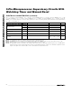
ELECTRICAL CHARACTERISTICS (continued)
(V
CC
= +4.75V to +5.5V for MAX82_L, V
CC
= +4.5V to +5.5V for MAX82_M, V
CC
= +3.15V to +3.6V for MAX82_T, V
CC
= +3V
to +3.6V for MAX82_S, V
CC
= +2.7V to +3.6V for MAX82_R, V
CC
= +2.38V to +2.75V for MAX82_Z, V
CC
= +2.25V to +2.75V for
MAX82_Y, T
A
= T
MIN
to T
MAX
, T
A
= -40°C to +85°C (SC70), T
A
= -40°C to +125°C (SOT23), unless otherwise noted. Typical values
are at T
A
= +25°C.) (Note 1)