
Datasheet


MAX823/MAX824/MAX825
5-Pin Microprocessor Supervisory Circuits With
Watchdog Timer and Manual Reset
6 _______________________________________________________________________________________
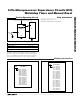
Pin Description
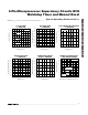
MAX823
MAX824
MAX825
V
CC
V
CC
WDI
(MAX823/MAX824
ONLY)
1.25V
GND
RESET
(MAX824/MAX825
ONLY)
RESET
MR
(MAX823/MAX825
ONLY)
RESET
GENERATOR
WATCHDOG
TIMER
WATCHDOG
TRANSITION
DETECTOR
FUNCTION
1 1
Active-Low Reset Output. Pulses low for 200ms when triggered, and remains
low whenever V
CC
is below the reset threshold or when MR is a logic low. It
remains low for 200ms after one of the following occurs: V
CC
rises above the
reset threshold, the watchdog triggers a reset, or MR goes low to high.
2 2 Ground
3 —
Manual Reset Input. A logic low on MR asserts reset. Reset remains asserted as
long as MR is held low and for 200ms after MR returns high. The active-low input
has an internal 52kΩ pullup resistor. It can be driven from a CMOS logic line or
shorted to ground with a switch. Leave open or connect to V
CC
if unused.
— 3
Active-High Reset Output. Inverse of RESET.
5 5 Supply Voltage
4 4
Watchdog Input. If WDI remains either high or low for longer than the watch-
dog timeout period, the internal watchdog timer runs out and a reset is trig-
gered. The internal watchdog timer clears whenever reset is asserted, or
whenever WDI sees a rising or falling edge. If WDI is left unconnected or is
connected to a three-stated buffer output, the watchdog feature is disabled.
NAME
1
RESET
2 GND
4
MR
3 RESET
5 V
CC
— WDI
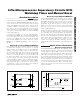
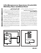
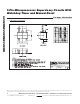
Figure 1. Functional Diagram
MAX824MAX823 MAX825
PIN