
Datasheet


MAX823/MAX824/MAX825
5-Pin Microprocessor Supervisory Circuits With
Watchdog Timer and Manual Reset
8 _______________________________________________________________________________________
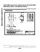
Interfacing to µPs with
Bidirectional Reset Pins
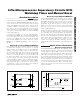
The RESET output maximum pullup current is 800µA for
L/M versions (400µA for T/S/R/Z/Y versions). This allows
µPs with bidirectional resets, such as the 68HC11, to
force RESET low when the MAX823/MAX824/MAX825
are pulling RESET high (Figure 4).
Negative-Going V
CC
Transients
These supervisors are relatively immune to short-
duration, negative-going V
CC
transients (glitches), which
usually do not require the entire system to shut down.
Resets are issued to the µP during power-up, power-
down, and brownout conditions.
The Typical Operating Characteristics show a graph of
the MAX823_’s Maximum V
CC
Transient Duration vs.
Reset Threshold Overdrive, for which reset pulses are
not generated. The graph was produced using nega-
tive-going V
CC
pulses, starting at 5V and ending below
the reset threshold by the magnitude indicated (reset
threshold overdrive). The graph shows the maximum
pulse width that a negative-going V
CC
transient can
typically have without triggering a reset pulse. As the
amplitude of the transient increases (i.e., goes farther
below the reset threshold), the maximum allowable
pulse width decreases.
An optional 0.1µF bypass capacitor mounted close to
V
CC
provides additional transient immunity.
Watchdog Software Considerations
(MAX823/MAX824)
One way to help the watchdog timer monitor software
execution more closely is to set and reset the watchdog
input at different points in the program, rather than
pulsing the watchdog input high-low-high or low-high-
low. This technique avoids a stuck loop, in which the
watchdog timer would continue to be reset inside the
loop, keeping the watchdog from timing out.
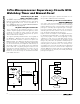
Figure 5 shows an example of a flow diagram where the
I/O driving the watchdog input is set high at the begin-
ning of the program, set low at the beginning of every
subroutine or loop, then set high again when the pro-
gram returns to the beginning. If the program should
hang in any subroutine, the problem would quickly be
corrected, since the I/O is continually set low and the
watchdog timer is allowed to time out, causing a reset
or interrupt to be issued. As described in the Watchdog
Input Current section, this scheme results in higher time
average WDI input current than does leaving WDI low
for the majority of the timeout period and periodically
pulsing it low-high-low.
MAX823
MAX824
MAX825
µP
V
CC
V
CC
V
CC
V
CC
GND
GND
RESET
I
SOURCE
MAX = 800µA L, M
400µA T, S, R, Z, Y
RESET
GENERATOR
Figure 4. Interfacing to µPs with Bidirectional Resets
START
SET WDI
HIGH
PROGRAM
CODE
SUBROUTINE OR
PROGRAM LOOP
SET WDI LOW
RETURN
Figure 5. Watchdog Flow Diagram