
Datasheet

MAX8569A/MAX8569B
200mA Step-Up Converters in 6-Pin
SOT23 and TDFN
6 _______________________________________________________________________________________
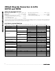
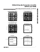
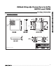
SHUTDOWN RESPONSE
(R
LOAD
= 33Ω)
MAX8569 toc13
2V
3.3V
2V/div
V
OUT
V
SHDN
100µs/div
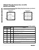
Typical Operating Characteristics (continued)
(Circuit of Figure 2, V
OUT
= 3.3V, V
BATT
= +2V, T
A
= +25°C, circuit of Figure 1, T
A
= +25°C, unless otherwise noted.)
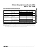
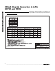
SWITCHING WAVEFORMS
(R
LOAD
= 33Ω)
MAX8569 toc14
100mV/div
2V/div
500mA/div
V
OUT
(AC-COUPLED)
I
L
V
LX
10µs/div
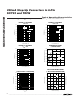
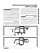
Pin Description
PIN
MAX8569A
MAX8569B
NAME
FUNCTION
11SHDN
Shutdown Input. Drive SHDN low to place the MAX8569 in shutdown mode. SHDN can be
used for a low-battery cutoff (1.228V threshold). See the Low-Battery Cutoff section for
details. Drive SHDN high for normal operation.
2 2 BATT
Battery Voltage Connection. Connect BATT to a 1.5V to 5.5V supply. Bypass BATT to GND
with a 10µF or larger ceramic capacitor.
3 3 GND Ground
44LX
Inductor Connection. Connect the switched side of the inductor to LX. During shutdown,
LX is connected to OUT.
5 5 OUT
Output Voltage. Bypass OUT to GND with a 10µF or larger ceramic capacitor. During
shutdown, OUT is connected to LX. OUT is also the bootstrapped supply input for the IC.
6 — FB
Feedback Input. Connect FB to the center tap of an external resistor-divider from OUT to
GND to set the output voltage. V
FB
regulates to 1.228V.
— 6 RST
Reset Output. RST is an open-drain output that goes high impedance when the output
voltage rises above 90% of the nominal regulation voltage. RST pulls low when the output
is below 90% of the nominal regulation voltage. RST is high impedance during shutdown.
——EP
Exposed Paddle (TDFN Package Only). Connect to the PC board ground plane for
increased thermal performance.