MAXSANTAFEEVSYS User Manual Rev 0; 5/14 For pricing, delivery, and ordering information, please contact Maxim Direct at 1-888-629-4642, or visit Maxim Integrated’s website at www.maximintegrated.com. Maxim Integrated cannot assume responsibility for use of any circuitry other than circuitry entirely embodied in a Maxim Integrated product. No circuit patent licenses are implied. Maxim Integrated reserves the right to change the circuitry and specifications without notice at any time.
MAXSANTAFEEVSYS User Manual Table of Contents 1 2 3 4 5 6 7 Introduction ......................................................................................................................................... 3 1.1 Ordering Information .................................................................................................................. 3 1.2 Package Contents...................................................................................................................... 3 1.
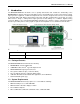
MAXSANTAFEEVSYS User Manual 1 Introduction The MAXSANTAFEEVSYS kit allows users to quickly demonstrate and evaluate the functionality of the MAXREFDES5 4-channel analog front-end (AFE) reference design without the need for a bench power supply, signal generator equipment, or Xilinx development kit. The reference design board connects to a PC through an included USB-to-SPI adaptor that provides both power and data communication to the board.
MAXSANTAFEEVSYS User Manual 1.4 Functional Diagram MAX8510 LDO MAX6133 VREF MAX9632 OpAmps (on 2 of 4-Ch) MAX6126 VREF OA MAXQ622 Controller MAX5216 16-bit DAC MAX1301 16-bit ADC OA MAX1659 LDO MAX256 Xfmr Driver MAX14850 Dig.
MAXSANTAFEEVSYS User Manual 2 Software Installation There are two Windows GUI applications included with MAXSANTAFEEVSYS used for: • Generating analog test signals with the MAX5216DACLITE board in order to evaluate the performance ® of the AFE reference design. This application is created using National Instruments LabVIEW . The NI LabVIEW Run-Time Engine (RTE) must be installed in order to install and execute the MAX5216DACLITE GUI application.
MAXSANTAFEEVSYS User Manual 3 Connections This section describes the basic connections with the MAXSANTAFEEVSYS kit. Two available USB ports are required for operating the MAXSANTAFEEVSYS kit setup. If needed, copy the \MAXREFDES5\ and \USB2PMB1\ directories from the USB flash drive to your PC to free up a USB port. All boards derive power from the USB ports. The USB2PMB1 board includes on-board DC-DC conversion for providing 3.3V DC to the MAXREFDES5 AFE board (or any other 3.3V Pmod Type 2A board).
MAXSANTAFEEVSYS User Manual 3.3 MAXREFDES5 4-Ch AFE Board Connect the MAXREFDES5 board to the USB2PMB1 adaptor. Both connectors should be on the same side of the PCB when mated together as shown below. 3.3.1 Analog Signal Connections The following table summarizes the different connection options for the MAXSANTAFEEVSYS kit. Note the input range of the MAXREFDES5 analog inputs exceeds the output capabilities of the MAX5216DACLITE board included with the kit.
MAXSANTAFEEVSYS User Manual 4 Graphical User Interfaces Before launching the GUI applications, make sure the USB2PMB1 and MAX5216DACLITE boards are connected to the PC as described in the previous section. 4.1 GUI for MAXREFDES5 With the USB2PMB1 board connected, run (double-click) the PMOD_SPI.exe GUI application located in the \MAXREFDES5\ directory.
MAXSANTAFEEVSYS User Manual 4.1.2 Sampling Controls The GUI provides the user with two options for the sampling of data from the MAXREFDES5. The Sample button captures a discrete number of samples as selected in the No. of Samples drop down menu and displays the results. To start continuously collecting and displaying measurement data, press the Sample Continuously button. When enabled, the button changes its text to Stop Sampling. In this mode, the No.
MAXSANTAFEEVSYS User Manual 4) Plot View Options: i. Plot Counts: This option plots the ADC code itself on the Y-axis with the number of samples on the x-axis. ii. Plot Volts: This option plots the converted Voltage value. iii. Plot Current: Plots the current measured across the 250Ω shunt resistance on the AIN2 input. iv. Plot Temp: Reserved for future use.
MAXSANTAFEEVSYS User Manual 4.1.4 Calibration For precision results, it is recommended to calibrate the MAXREFDES5 hardware using the function provided with the GUI. Calibration parameters for each combination of input channel and input range are stored in a local file in the GUI directory on the PC. Press the Calibration button to open a window with the calibration parameters. i. Save Settings to File: Saves the current settings to a local file on the PC.
MAXSANTAFEEVSYS User Manual 4.2 GUI for MAX5216DACLITE With the MAX5216DACLITE board connected, click on the MAX5216DACLite shortcut found in the Start menu. The GUI will automatically connect to the MAX5216DACLITE hardware upon initialization. This section describes the basic functionality needed to generate test signals for evaluating the MAXREFDES5 design. For more information on the MAX5216DACLITE GUI, refer to the MAX5216DACLITE data sheet.
MAXSANTAFEEVSYS User Manual 5 Hardware Description This section provides more information on the hardware design of the three boards including schematics, bill of materials, and PCB layout files. 5.1 MAXREFDES5 The MAXREFDES5 reference design is a 4-channel analog front-end (AFE) that accepts -10V to +10V, 0 to 10V, and 4–20mA current loop signals.
MAXSANTAFEEVSYS User Manual 6 Contact Information For more information about Maxim Integrated products, contact technical support at www.maximintegrated.com/support. 7 Trademarks LabVIEW is a registered trademark of National Instruments Corp. MICROWIRE is a registered trademark of National Semiconductor Corp. Pmod is a trademark Digilent Inc. Windows is a registered trademark and registered service mark and Windows XP is a registered trademark of Microsoft Corporation.
MAXSANTAFEEVSYS User Manual 8 Revision History REVISION NUMBER 0 Rev 0 REVISION DATE 5/14 DESCRIPTION Initial release PAGES CHANGED — 15