
Datasheet

_______________General Description
The MX7534/MX7535 are high-performance, CMOS,
monolithic, 14-bit digital-to-analog converters (DACs).
Wafer-level, laser-trimmed, thin-film resistors and tempera-
ture-compensated NMOS switches assure operation over
the full operating temperature range with exceptional lin-
ear and gain stability.
The MX7534 accepts right-justified data in two bytes from
an 8-bit bus, while the MX7535 operates with a 14-bit data
bus with separate MS-byte and LS-byte select controls. In
addition, all digital inputs are compatible with both TTL and
5V CMOS-logic levels. The MX7534/MX7535 are intended
for unipolar operation, but may be operated as bipolar
DACs with additional external components. Both devices
are protected against CMOS latchup, and neither requires
the use of external Schottky protection diodes.
The MX7534 is available in 20-pin narrow (0.3") DIP, wide
SO, or PLCC packages. The MX7535 is available in
28-pin, 600 mil wide DIP, wide SO, or PLCC packages.
________________________Applications
Machine and Motion Control Systems
Automatic Test Equipment
Digital Audio
µP-Controlled Calibration Circuitry
Programmable-Gain Amplifiers
Digitally Controlled Filters
Programmable Power Supplies
____________________________Features
♦ 14-Bit Monotonic Over Full Temperature Range
♦ Full 4-Quadrant Multiplication
♦ µP-Compatible, Double-Buffered Inputs
♦ Exceptionally Low Gain Tempco (2.5ppm/°C)
♦ Low Output Leakage (<20nA) Over Temp.
♦ Low Power Consumption
♦ TTL and CMOS Compatible
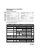
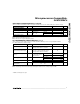
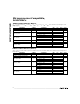
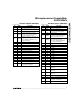
______________Ordering Information
Ordering Information continued at end of data sheet.
*
Dice are tested at +25°C, DC parameters only.
MX7534/MX7535
Microprocessor-Compatible,
14-Bit DACs
________________________________________________________________
Maxim Integrated Products
1
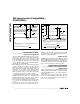
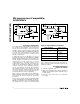
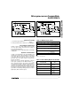
MX7534
DAC REGISTER
MS
INPUT
REGISTER
LS
INPUT
REGISTER
14
6
8
2
3
4
5
15
16
18
17
20
6
7–14
19
14-BIT DAC
CONTROL
LOGIC
1
REF
RFB
IOUT
AGNDS
AGNOF
A1
A0
CS
WR
V
DD
D7–D0 DGND V
SS
Functional diagrams continued at end of data sheet.
_______________Functional Diagrams
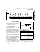
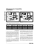
_________________Pin Configurations
19-1116; Rev 1; 11/96
For free samples & the latest literature: http://www.maxim-ic.com, or phone 1-800-998-8800
PART TEMP. RANGE PIN-PACKAGE INL (LSBs)
MX7534KN
0°C to +70°C 20 Plastic DIP ±1
MX7534JN 0°C to +70°C 20 Plastic DIP ±2
MX7534KCWP
0°C to +70°C 20 SO ±1
MX7534JCWP 0°C to +70°C 20 SO ±2
MX7534KP 0°C to +70°C 20 PLCC ±1
MX7534JP 0°C to +70°C 20 PLCC ±2
MX7534J/D 0°C to +70°C Dice* ±2
MX7534BQ -25°C to +85°C 20 CERDIP ±1
MX7534AQ -25°C to +85°C 20 CERDIP ±2
MX7534BD
-25°C to +85°C 20 Ceramic SB ±1
MX7534AD -25°C to +85°C 20 Ceramic SB ±2
MX7534KEWP -40°C to +85°C 20 SO ±1
MX7534JEWP -40°C to +85°C 20 SO ±2
MX7534TQ -55°C to +125°C 20 CERDIP ±1
MX7534SQ -55°C to +125°C 20 CERDIP ±2
MX7534TD -55°C to +125°C 20 Ceramic SB ±1
MX7534SD -55°C to +125°C 20 Ceramic SB ±2
20
19
18
17
16
15
14
13
1
2
3
4
5
6
7
8
V
SS
V
DD
CS
WR
AGNDS
IOUT
RFB
REF
TOP VIEW
A0
A1
D0
D1
D6
D7
DGND
AGNDF
12
11
9
10
D2
D3
D4
MX7535 at end of data sheet.
D5
DIP/SO/PLCC/Ceramic SB
MX7534