
Datasheet


General Description
The DG411F/DG412F/DG413F are quad, single-pole/sin-
gle-throw (SPST), fault-protected analog switches. They
are pin compatible with the industry-standard nonpro-
tected DG411/DG412/DG413. These new switches fea-
ture fault-protected inputs and Rail-to-Rail
signal-
handling capability. All terminals are protected from
overvoltage faults up to ±36V with power on and up to
±40V with power off. During a fault condition, the COM,
NO, or NC terminal becomes an open circuit and only
microamperes of leakage current flow from the source.
On-resistance is 35Ω (max) and is matched between
switches to 1.5Ω (max) at +25°C.
The DG411F has four normally closed (NC) switches.
The DG412F has four normally open (NO) switches.
The DG413F has two NC and two NO switches. These
CMOS switches operate with dual power supplies rang-
ing from ±4.5V to ±20V or a single supply between +9V
and +36V. All digital inputs have +0.8V and +2.4V logic
thresholds, ensuring both TTL and CMOS logic com-
patibility when using ±15V or a single +12V supply.
For supply voltages of ±5V, +5V, and +3V, refer to the
MAX4711/MAX4712/MAX4713 data sheet.
Applications
Communication Systems
Signal Routing
Test Equipment
Data Acquisition
Industrial and Process Control Systems
Avionics
Redundant/Backup Systems
Features
♦ No Power-Supply Sequencing Required
♦ Rail-to-Rail Signal Handling
♦ All Switches Off with Power Off
♦ All Switches Off when V+ is Off and V- is On
♦ ±40V Fault Protection with Power Off
♦ ±36V Fault Protection with ±15V Supplies
♦ Control Line Fault Protection from
V- - 0.3V to V- + 40V
♦ Pin Compatible with Industry-Standard
DG411/DG412/DG413
♦ 20ns (typ) Fault Response Time
♦ 35Ω (max) R
ON
with ±15V Supplies
♦ ±4.5V to ±20V Dual Supplies
♦ +9V to +36V Single Supply
♦ TTL- and CMOS-Compatible Logic Inputs with
±15V or Single +9V to +15V Supplies
DG411F/DG412F/DG413F
Quad, Rail-to-Rail, Fault-Protected,
SPST Analog Switches
19-2418; Rev 0; 4/02
For pricing, delivery, and ordering information, please contact Maxim/Dallas Direct! at
1-888-629-4642, or visit Maxim’s website at www.maxim-ic.com.
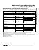
Ordering Information
PART TEMP RANGE PIN-PACKAGE
DG411FEUE -40°C to +85°C 16 TSSOP
DG411FDY -40°C to +85°C 16 SO
DG411FDJ -40°C to +85°C 16 Plastic DIP
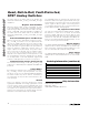
N.C. = NOT CONNECTED. SWITCHES SHOWN FOR LOGIC 0 INPUT.
ALL SWITCHES ARE OFF WITH POWER REMOVED.
TOP VIEW
DIP/TSSOP/SO
DG411F
LOGIC SWITCH
0
1
ON
OFF
16
15
14
13
12
11
10
9
1
2
3
4
5
6
7
8
IN2
COM2
NC2
V+
V-
NC1
COM1
IN1
DG411F
N.C.
NC3
COM3
IN3
IN4
COM4
NC4
GND
Pin Configurations
________________________________________________________________ Maxim Integrated Products 1
Rail-to-Rail is a registered trademark of Nippon Motorola, Ltd.
Pin Configurations continued at end of data sheet.
Functional Diagram appears at end of data sheet.
Ordering Information continued at end of data sheet.