
User`s guide
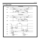

DS5001FP
24 of 27
NOTES:
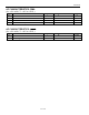
All parameters apply to both commercial and industrial temperature operation unless otherwise noted.
1) All voltages are referenced to ground.
2) Maximum operating I
CC
is measured with all output pins disconnected; XTAL1 driven with t
CLKR
,
t
CLKF
= 10ns, V
IL
= 0.5V; XTAL2 disconnected; RST = PORT0 = V
CC
, MSEL = V
SS
.
3) Idle mode, I
IDLE
, is measured with all output pins disconnected; XTAL1 driven with t
CLKR
,
t
CLKF
= 10ns, V
IL
= 0.5V; XTAL2 disconnected; PORT0 = V
CC
, RST = MSEL = V
SS
.
4) Stop mode, I
STOP
, is measured with all output pins disconnected; PORT0 = V
CC
; XTAL2 not
connected; RST = MSEL = XTAL1 = V
SS
.
5) Pin capacitance is measured with a test frequency: 1MHz, T
A
= +25°C.
6) I
CCO1
is the maximum average operating current that can be drawn from V
CCO
in normal operation.
7) I
LI
is the current drawn from V
LI
input when V
CC
= 0V and V
CCO
is disconnected.
8) V
CCO2
is measured with V
CC
< V
LI
, and a maximum load of 10µA on V
CCO
.
9) Crystal startup time is the time required to get the mass of the crystal into vibrational motion from the
time that power is first applied to the circuit until the first clock pulse is produced by the on-chip
oscillator. The user should check with the crystal vendor for a worst-case specification on this time.
10) This parameter applies to industrial temperature operation.
11) PF pin operation is specified with V
BAT
³ 3.0V.