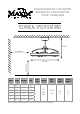
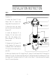
INSTALLATION AND SAFETY INSTRUCTIONS READ AND SAVE THESE INSTRUCTIONS ITEM NO.: F993001DWBK TECHNICAL SPECIFICATIONS 460mm ≥1000mm ≥2100mm 695mm Speed Amps Wattage RPM 1 2 3 4 5 6 0.05 0.06 0.09 0.14 0.21 0.32 2.2 3.4 5.6 9.7 15 23.8 88 135 185 235 275 325 No. of blades Voltage Light bulb Nett weight Gross weight 3 110120V~ 60Hz 1 x 32W LED 9.6 kg 13.1 kg Specifications & measurements shown are subject to ±5% variations.
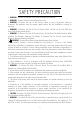
SAFETY PRECAUTION • WARNING –To make sure power is off before attempting installation. • WARNING – Support Directly From Building Structure. • WARNING –To reduce the risk of fire, electric shock, or injury to persons, unplug or disconnect the appliance from the power supply before the fan installation, cleaning, or servicing. • WARNING –To Reduce The Risk Of Fire Or Electric Shock, Do Not Use This Fan With Any Solid-State Speed Control Device.
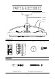
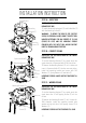
PARTS & ACCESSORIES Canopy Downrod Housing Blade Transmitter Kit Transmitter Holder Battery R2 Wall Screw x 2 0 + 32 C Transmitter 3V Assembly Kit Expansion Bolt x 4 Self Tapping Screw &Washer x 4 3
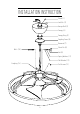
INSTALLATION INSTRUCTION Screw (1) Lock Pin (2) Hanger Ball (3) Canopy (4) Canopy Ring (5) Coupling Cover (6) Downrod (7) Clevis Pin (8) Bolt (10) Nut (9) Spring Washer (11) Flat Washer (12) Coupling (14) Set Screws (13) 4
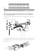
INSTALLATION INSTRUCTION STEP 1 1) Remove the Clevis Pin (8), Nut (9), Spring Washers (11), Flat Washers (12) & Bolt (10) on Coupling (14). 2 2) Loosen the Screw (1) from Hanger Ball (3), remove the Hanger Ball (3) and Lock Pin (2). 3 1 3) Route the wires and safety wire from the motor through the Downrod (7). 7 4) Install the Downrod (7) to Coupling (14) and secure with Bolt (10), Flat Washer (12), Spring Washer (11), Nut (9) & Clevis pin (8).
INSTALLATION INSTRUCTION STEP 2A – OUTLET BOX Outlet Box(3) Mounting Bracket (1) Mounting Screws (2) SWITCH OFF THE ELECTRICAL MAINS AT THE CIRCUIT BREAKER FUSE BOX. 1) Install the mounting bracket (1) onto Outlet Box (3) with the Mounting Screws(2). WARNING - TO REDUCE THE RISK OF FIRE, ELECTRIC SHOCK, OR PERSONAL INJURY, MOUNT TO OUTLET BOX MARKED (ACCEPTABLE FOR FAN SUPPORT OF 15.
INSTALLATION INSTRUCTION STEP 3 1) Raise the fan and place the hanger ball onto mounting bracket. 2) Rotate the fan until the notch on hanger ball snapped into the slot on mounting bracket and sits firmly. NOTE : THE DOWNROD AND HANGER BALL SHOULD NOT ROTATE IF THIS STEP IS DONECORRECTLY. 3) Tighten the safety wire clamp. 4) Place ring of safety wire through the expansion bolt or self tapping screw and fix it to the building structure. Safety Wire Clamp 5) Connect the wire connector plugs correctly.
INSTALLATION INSTRUCTION STEP 4 MOTOR U MOTOR V MOTOR W LIGHT N LIGHT L SWITCH OFF THE ELECTRICAL MAINS AT THE CIRCUIT BREAKER FUSE BOX. 1) Connect wires from controller to power supply with wire connectors. Controller (Receiver) 2) Insert the controller and LED Driver into the space of the mounting bracket, and tidy up the wiring.
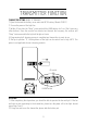
TRANSMITTER FUNCTION TRANSMITTER SETTING (MODEL: FCT6000WT) 1) Open the transmitter battery cover and install DC3V battery. (Model: CR2032) 2) Turn on the power of the light fan. 3) Within 30 sec after the “Beep”, press and hold the LEARN button for 3 sec. (Don’t press any other buttons.) Once the receiver has detected and learned the frequency, the receiver will “Beep” twice mean while the light will bright out twice. 4) Programming/self-learning process is completed and transmitter is ready to use.
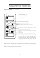
TRANSMITTER FUNCTION TRANSMITTER FUNCTION (MODEL: FCT6000WT) Operating Indicator Fan Speed Indicator (1~6) Timing Indicator (1, 3, 6hr) Turns off the fan Fan speed control (increasing) Fan speed control (decreasing) Timing the fan (Auto off after 1/3/6 hrs) Natural Wind: Fan speed changes within its range creating gentle natural wind effect. Forward or reverse operation: change fan rotating direction.
TRANSMITTER FUNCTION Forward Fan rotates anti-clockwise creating a downward airflow delivering a cooling effect. Suitable for hot weather condition or air-conditioned condition. Reverse Fan rotates clockwise creating an upward airflow moving warm air off the ceiling areas. This function works best at lower fan speed. Suitable for cold weather or air-conditioned condition.
MAINTENANCE Due to the fan’s natural movement, connections may get loose after a period of usage. To ensure a proper and safety usage, inspect the suspension system and tighten all connections every 6 months. Cleaning Cleaning your fan periodically will prolong its useful life. Basic cleaning procedures are as follows: 1. Please shut off the power before you clean the light fan and replace the bulbs. 2. The bulbs and nearby parts will be still hot after the power is shut off.