
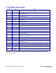
Specifications

Reference Design HFRD-25.2 (Rev.8; 01/09) Maxim Integrated Products
Page 31 of 42
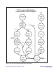
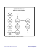
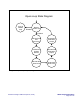
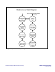
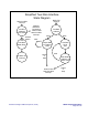
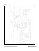
Figure 5. APC loop and modulation-compensation state diagram.
A
PC Loop and Modulation-
Compensation State Diagram
Compare
Value to
Calibration
Value
Inc
Integrato
r
Counter
Compare
Counter Value
to Terminal
Count
A
pply Mod
K-Facto
r
Comp
Inc
PWM Value
Greater Than
Dec
Integrator
Counter
Compare
Counter Value
to 0
Less Than
Counter =
Terminal Count
Reset
Counter
Output New
Value
Dec
PWM Value
Counter = 0
Not
=
Dec Control
Counter
Bit 0 = 0
Exit
Bit 0 = 1
A
pply Mod
Temperature
Comp
Call Mod
Integrato
r
Equal
Init APC Loop
Counte
r
Call VCC
Comp
Exit
Update
Mod
Output