
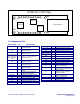
Specifications

Reference Design HFRD-25.2 (Rev.8; 01/09) Maxim Integrated Products
Page 32 of 42
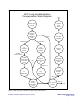
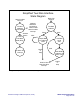
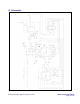
Figure 6. Simplified update monitors and memory state diagram.
Update Monitors and
Memory State Diagram
Quick
Conversion to
Clear Prev.
Temp
Conversion/
Update
Bias
Conversion/
Update
Quick
Conversion to
Clear Prev.
V
CC
Conversion/
Update
Mode Bit 2 = 0
Exit
RSSI
Conversion/
Update
V
CC
Conversion/
Update
Read
EEPROM
01h to 0Ah
Mode Bit 2 = 1
Update SRAM
Registers
Exit