
User guide

General Description
The MAX1416 evaluation kit (EV kit) is an assembled and
tested printed-circuit board (PCB) that demonstrates the
MAX1416 multichannel, 16-bit, sigma-delta data-acquisi-
tion system. Windows
®
98/2000/XP-compatible software
provides a convenient user interface to exercise the fea-
tures of the MAX1416.
Order the complete evaluation system (EV system)
(MAX1416EVC16) for a comprehensive evaluation of the
MAX1416 using a personal computer. Order the EV kit
(MAX1416EVKIT) if the 68HC16MODULE-DIP has been
purchased with a previous Maxim EV system, or for cus-
tom use in other microcontroller (µC)-based systems.
To evaluate the MAX1415, request a free sample of the
MAX1415EUE. To evaluate the MX7705, request a free
sample of the MX7705EUE.
Features
♦ Proven PCB Board Layout
♦ Complete Evaluation System
♦ Convenient On-Board Test Points
♦ Fully Assembled and Tested
♦ EV Kit Software Supports Windows 98/2000/XP
with RS-232/COM Port
♦ EV Kit Software Supports Windows 2000/XP with
USB Port
Evaluate: MAX1416/MAX1415/MX7705
MAX1416 Evaluation Kit/Evaluation System
________________________________________________________________ Maxim Integrated Products 1
19-3084; Rev 1; 5/07
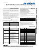
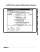
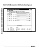
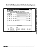
Component Lists
For pricing, delivery, and ordering information, please contact Maxim/Dallas Direct! at
1-888-629-4642, or visit Maxim’s website at www.maxim-ic.com.
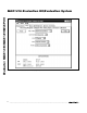
Ordering Information
MAX1416 EV Kit
Windows is a registered trademark of Microsoft Corp.
PART
TEMP RANGE
INTERFACE TYPE
MAX1416EVC16
0°C to +70°C*
Windows software
MAX1416EVKIT
0°C to +70°C*
User supplied
*This limited temperature range applies to the EV kit PCB only.
The MAX1416 IC temperature range is -45°C to +85°C.
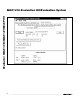
Note: The MAX1416 software is designed for use with the
complete EV system (MAX1416EVC16). It includes a
68HC16MODULE-DIP module, USBTO232, and a
MAX1416EVKIT. If the MAX1416 evaluation software is not
used, the MAX1416EVKIT board can be purchased by itself,
without the µC.
PART
QTY
DESCRIPTION
MAX1416EVKIT
1
MAX1416 evaluation kit
68HC16MODULE-DIP
1
68HC16 µC module
USBTO232+
1
U S B- to- C OM p or t ad ap ter b oar d
DESIGNATION QTY DESCRIPTION
C1–C4, C10,
C11
6
0.01µF, 10V X7R ceramic capacitors
(radial leaded)
C5 1
0.01µF ±10%, 50V X7R ceramic
capacitor (0603)
Taiyo Yuden UMK107B103KZ
TDK C1608X7R1H103KT
C6 1
4.7µF ±20%, 10V X5R ceramic
capacitor (1206)
Taiyo Yuden LMK316BJ475ML
TDK C3216X5R1A475MT
C7, C8 2
22pF ±5%, 50V C0G ceramic
capacitors (0603)
TDK C1608C0G1H220J
C9, C12, C13 3
0.1µF ±10%, 50V X7R ceramic
capacitors (0805)
Taiyo Yuden UMK212BJ104KG
TDK C2012X7R1H104KT
C14 1
1µF, 10V X7R ceramic capacitor
(0805)
TDK C2012X7R1A105K
DESIGNATION QTY DESCRIPTION
H1 1 8-pin header
J1 1 2 x 20 right-angle socket
JU1 1 2-pin header
JU2 1 2-pin header
JU3 1 3-pin header
JU4 1 2-pin header
R1–R4 4 10Ω ±5% resistors (axial leaded)
R5, R6 2 10Ω ±5% resistors (1206)
TB1 1
0.200in 2-circuit screw terminal
TB2, TB3 2
0.200in 3-circuit screw terminal
blocks
U1 1 MAX1416EUE (16-pin TSSOP)
U2 1 MAX873ACSA
U3, U4 2 MAX1840EUB
Y1 1
4.9152MHz crystal (HC49/US),
parallel resonant, 20pF load
ECS 49-20-4
— 4 Shunts (JU1–JU4)
— 1 PCB: MAX1416 Evaluation Kit
MAX1416 EV System
+Denotes lead-free and RoHS-complaint.