
Datasheet


±15kV ESD-Protected, Slew-Rate-Limited,
Low-Power, RS-485/RS-422 Transceivers
It takes the drivers and receivers longer to become
enabled from the low-power shutdown state (t
ZH(SHDN
)
,
t
ZL(SHDN)
) than from the operating mode (t
ZH
, t
ZL
). (The
parts are in operating mode if the RE, DE inputs equal a
logical 0,1 or 1,1 or 0, 0.)
Driver Output Protection
Excessive output current and power dissipation caused
by faults or by bus contention are prevented by two
mechanisms. A foldback current limit on the output stage
provides immediate protection against short circuits over
the whole common-mode voltage range (see
Typical
Operating Characteristics
). In addition, a thermal shut-
down circuit forces the driver outputs into a high-imped-
ance state if the die temperature rises excessively.
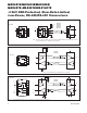
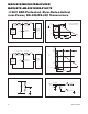
Propagation Delay
Many digital encoding schemes depend on the differ-
ence between the driver and receiver propagation
delay times. Typical propagation delays are shown in
Figures 19–22 using Figure 18’s test circuit.
The difference in receiver delay times, t
PLH
- t
PHL
, is
typically under 13ns for the MAX481E, MAX485E,
MAX490E, MAX491E, and MAX1487E, and is typically
less than 100ns for the MAX483E and MAX487E–
MAX489E.
The driver skew times are typically 5ns (10ns max) for
the MAX481E, MAX485E, MAX490E, MAX491E, and
MAX1487E, and are typically 100ns (800ns max) for the
MAX483E and MAX487E–MAX489E.
Typical Applications
The MAX481E, MAX483E, MAX485E, MAX487E–
MAX491E, and MAX1487E transceivers are designed for
bidirectional data communications on multipoint bus
transmission lines. Figures 25 and 26 show typical net-
work application circuits. These parts can also be used as
line repeaters, with cable lengths longer than 4000 feet.
To minimize reflections, the line should be terminated at
both ends in its characteristic impedance, and stub
lengths off the main line should be kept as short as possi-
ble. The slew-rate-limited MAX483E and MAX487E–
MAX489E are more tolerant of imperfect termination.
Bypass the V
CC
pin with 0.1µF.
Isolated RS-485
For isolated RS-485 applications, see the MAX253 and
MAX1480 data sheets.
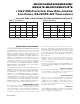
Line Length vs. Data Rate
The RS-485/RS-422 standard covers line lengths up to
4000 feet. Figures 23 and 24 show the system differen-
tial voltage for the parts driving 4000 feet of 26AWG
twisted-pair wire at 110kHz into 100Ω loads.
100pF
100pF
R = 54Ω
A
B
Y
D
Z
R
RECEIVER
OUT
TTL IN
t
R
, t
F
< 6ns
Figure 18. Receiver Propagation Delay Test Circuit
MAX481E/MAX483E/MAX485E/
MAX487E–MAX491E/MAX1487E
Maxim Integrated
13