
Datasheet

±15kV ESD-Protected, Slew-Rate-Limited,
Low-Power, RS-485/RS-422 Transceivers
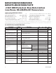
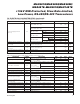
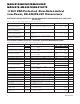
______________________________________________________________Pin Description
1 2
Receiver Output: If A > B by 200mV, RO will be high;
If A < B by 200mV, RO will be low.
2 —
Receiver Output Enable. RO is enabled when
–
R
—
E
–
is
low; RO is high impedance when
–
R
—
E
–
is high.
3 —
Driver Output Enable. The driver outputs, Y and Z, are
enabled by bringing DE high. They are high imped-
ance when DE is low. If the driver outputs are enabled,
the parts function as line drivers. While they are high
impedance, they function as line receivers if
–
R
—
E
–
is low.
4 3
Driver Input. A low on DI forces output Y low and out-
put Z high. Similarly, a high on DI forces output Y high
and output Z low.
6 —
Noninverting Receiver Input and Noninverting Driver
Output
— 6 Inverting Driver Output
— 5 Noninverting Driver Output
5 4 Ground
— — No Connect—not internally connected
8 1 Positive Supply: 4.75V ≤ V
CC
≤ 5.25V
— 7 Inverting Receiver Input
7 — Inverting Receiver Input and Inverting Driver Output
— 8 Noninverting Receiver Input
PIN
2
3
4
5
—
10
9
6, 7
1, 8, 13
14
11
—
12
RO
–
R
—
E
–
DE
DI
A
Z
Y
GND
N.C.
V
CC
B
B
A
FUNCTION
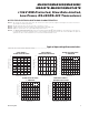
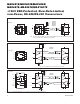
MAX489E
MAX491E
NAME
MAX488E
MAX490E
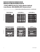
MAX481E/MAX483E
MAX485E/MAX487E
MAX1487E
MAX481E/MAX483E/MAX485E/
MAX487E–MAX491E/MAX1487E
Maxim Integrated
7