
Operating instructions


male cable. If the only available serial port uses a
25-pin connector, a standard 25-pin to 9-pin
adapter is required. The EV kit software checks the
modem status lines (CTS, DSR, DCD) to confirm
that the correct port has been selected.
7) Start the MAX1132 program by opening its icon in
the Start | Programs menu.
8) Turn on the power supply and slide SW1 to the ON
position on the 68HC16MODULE-DIP module.
Press the OK button to automatically connect and
download the KIT1132.C16 file to the module.
9) Apply the input signal across the pins of JU2.
Observe the readout on the screen.
Detailed Description
of Software
The evaluation software main window controls the
active control word bits, serial clock speed, and sam-
ple rate. It displays the voltage and output code, as
well as some statistics of the input signal. A separate
graph window shows the data changing in real time.
The update rate is limited to about 10 samples per sec-
ond, due to COM port bandwidth limitations.
Controls
The control word is divided into several fields. To
change the active control word, drop down the appro-
priate field’s combo box and select the desired option.
If the QSPI clock is set to STOP, the configuration data
is not sent until the READ button is clicked.
Statistics
The minimum and maximum fields show the lowest and
highest readings acquired. The average and RMS
fields show the running mean and root-mean-square of
the input signal. The Clear button resets the statistics.
To remove offset errors, first apply zero volts to the
active input channel, clear statistics, acquire some
samples, and then check Tare. This offset is now sub-
tracted from all subsequent voltage measurements.
Sampling
To sample data at rates up to 125ksps, select the
Sample menu item, make your selections, and click the
Begin Sampling button. Sample size is restricted to a
power of two to permit FFT processing once the data is
saved to a file. After the samples have been collected,
the data is automatically uploaded to the host and is
Evaluate: MAX1132/MAX1133
MAX1132 Evaluation Kit/Evaluation System
_______________________________________________________________________________________ 3
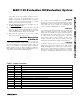
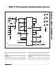
JUMPER POSITION
FUNCTION
— 1-2 Operate
JU1 Open SHDN is controlled by 68HC16 module
— 2-3 Shutdown
JU2 Closed Measure short circuit (zero volts)
— Open Apply input signal at JU2
JU3 Closed Illegal
— Open* Enable internal reference, or apply an external reference
JU4 Closed Disable internal reference
— Open* Enable internal reference
— 1 User-programmable output pin P2
JU5 2 User-programmable output pin P1
— 3 User-programmable output pin P0
Table 1. Jumper Functions
*Default configuration.