Maximal V Series Single Power Supply Access Power Controllers (Fused) Models Include: Maximal3V - 12VDC @ 5A or 24VDC @ 5.4A. - Sixteen (16) fuse protected outputs. Maximal5V - 12VDC @ 9A. - Sixteen (16) fuse protected outputs.. Maximal7V - 24VDC @ 9.4A. - Sixteen (16) fuse protected outputs. Installation Guide Rev. SF022607 More than just power.TM Installing Company: _______________ Service Rep.
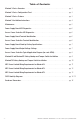
Table of Contents: Maximal V Series Overview. . . . . . . . . . . . . . . . . . . . . . . . . . . . . . . . . . . . . . . . . . . . . . . . . . . pg. 3 Maximal V Series Configuration Chart . . . . . . . . . . . . . . . . . . . . . . . . . . . . . . . . . . . . . . . . . . pg. 3 Maximal V Series Features . . . . . . . . . . . . . . . . . . . . . . . . . . . . . . . . . . . . . . . . . . . . . . . . . . . pg. 3 Maximal V Installation Instructions . . . . . . . . . . . . . . . . . . . . . . . . . . . . . . . .
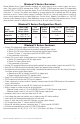
Maximal V Series Overview: Altronix Maximal Access Power/Controllers distribute and switch power to access control systems and accessories. They convert a 220VAC (working range 198VAC - 256VAC), 50/60Hz input into sixteen (16) independently controlled 12VDC or 24VDC fuse protected outputs. These Fail-Safe/Fail-Secure power outputs may be converted to dry form “C” contacts.
Maximal V Installation Instructions: Wiring methods shall be in accordance with the National Electrical Code/NFPA 70/ANSI, and with all local codes and authorities having jurisdiction. Product is intended for indoor use only. Power Supply Board LED Diagnostics (pg. 6) Access Power Controller LED Diagnostics (pg. 6) Power Supply Board Terminal Identification (pg. 6) Access Power Controller Terminal Identification (pg. 6) Power Supply Board Stand-by Battery Specifications (pg.
9. 10. 11. 12. (a) Normally Open [NO] input: For non-latching hook-up refer to Fig. 9, pg. 13. For latching hook-up refer to Fig. 10, pg. 13. (b) Normally Closed [NC] input: For non-latching hook-up refer to Fig. 11, pg. 14. For latching hook-up refer to Fig. 12, pg. 14. (c) FACP Signaling Circuit input trigger: Connect the positive (+) and negative (–) from the FACP signaling circuit output to the terminals marked [+ INP –].
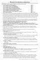
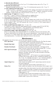
Power Supply Board LED Diagnostics: Red (DC) ON ON OFF OFF LED Green (AC) ON OFF ON OFF Red (Bat) ON OFF Power Supply Status Normal operating condition. Loss of AC. Stand-by battery supplying power. No DC output. Short circuit or thermal overload condition. No DC output. Loss of AC. Discharged battery. Battery Status Normal operating condition. Battery fail/low battery. Access Power Controller LED Diagnostics: LED LED 1- LED 8 (Red) Trg (Green) ON Output relay(s) energized.
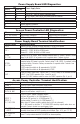
Power Supply Board Stand-by Battery Specifications: Altronix Model: Power Supply Board Maximal3 Battery 20 Min. of Backup 4 hr. of Backup 24 hr. of Backup N/A 5.0A N/A N/A 5.4A 0.7A N/A 200mA 1.2A AL600XB220 12VDC/40AH* (Refer to Fig. 1a, pg. 7 for Switch 24VDC/40AH* [SW1] location and position) Maximal5 AL1012XB220 (Factory set at 12VDC) 12VDC/12AH 9.0A Battery capacity for emergency stand-by: at least 20 min. Maximal7 AL1024XB2V (Factory set at 24VDC) 24VDC/12AH 24VDC/65AH* 7.
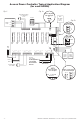
Access Power Controller Typical Application Diagram (for each ACM8): Fig. 2 Fig. 2a Intact = Dry Input Cut = Wet Input Normally Open (N.O.) Door Releasing Device FACP (Fire Alarm Control Panel) FACP Keypad Access Control Panel TRG C NO Fig.
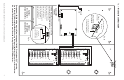
NO C NC FACP +INP- T + RETINTERFACE Fig. 3b Tamper Switch + + Power Control DC +INP- T + RETINTERFACE Enclosure AC NO C NC FACP Edge of Enclosure BAT FAIL NC C NO NC C NO AC FAIL To Access Control Panel or UL Listed Reporting Device Neutral MAIN MAIN Tamper Switch (not included) N OUTPUT 8 OUTPUT 7 OUTPUT 6 OUTPUT 5 OUTPUT 4 OUTPUT 3 OUTPUT 2 + + Power Control G 10A 250V 10A 250V 4 3 2 1 4 3 Fig. 3 - Maximal3V and Maximal5V L Ground Lug Line Input 220VAC 50/60Hz Fig.
NO C NC FACP +INP- T + RETINTERFACE Fig. 4a Tamper Switch + + Power Control DC +INP- T + RETINTERFACE Enclosure AC NO C NC FACP Edge of Enclosure BAT FAIL NC C NO NC C NO AC FAIL To Access Control Panel or UL Listed Reporting Device Neutral MAIN MAIN Tamper Switch (not included) N + + Power Control G 10A 250V 10A 250V 4 3 2 1 4 3 Fig.
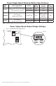
NEC Power-Limited Wiring Requirements for Maximal3V: Power-limited and non power-limited circuit wiring must remain separated in the cabinet. All power-limited circuit wiring must remain at least 0.25” away from any non power-limited circuit wiring. Furthermore, all power-limited circuit wiring and non power-limited circuit wiring must enter and exit the cabinet through different conduits. One such example of this is shown below. Your specific application may require different conduit knockouts to be used.
NEC Power-Limited Wiring Requirements for Maximal5V: Power-limited and non power-limited circuit wiring must remain separated in the cabinet. All power-limited circuit wiring must remain at least 0.25” away from any non power-limited circuit wiring. Furthermore, all power-limited circuit wiring and non power-limited circuit wiring must enter and exit the cabinet through different conduits. One such example of this is shown below. Your specific application may require different conduit knockouts to be used.
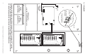
NEC Power-Limited Wiring Requirements for Maximal7V: Power-limited and non power-limited circuit wiring must remain separated in the cabinet. All power-limited circuit wiring must remain at least 0.25” away from any non power-limited circuit wiring. Furthermore, all power-limited circuit wiring and non power-limited circuit wiring must enter and exit the cabinet through different conduits. One such example of this is shown below. Your specific application may require different conduit knockouts to be used.
FACP Hook-Up Diagrams: Fig. 8 Polarity reversal input from FACP signaling circuit output (polarity is referenced in alarm condition): CUT JUMPER FACP FACP OUTPUT EOL INTERFACE TRG NO C NC FACP -- FROM FACP OUTPUT + CIRCUIT Fig. 9 Normally Open - Non-Latching FACP trigger input: FACP N.O. TRIGGER INPUT NO C NC FACP INTERFACE TRG Fig. 10 Normally Open FACP Latching trigger input with reset: FACP TRG N.O. TRIGGER INPUT JUMPER NO C NC N.C.
FACP Hook-Up Diagrams (cont’d): Fig. 11 Normally Closed - Non-Latching FACP trigger input: TRG INTERFACE FACP N.C. DRY TRIGGER INPUT NO C NC FACP JUMPER Fig. 12 Normally Closed - Latching FACP trigger input with reset: FACP TRG N.C. RESET SWITCH JUMPER Maximal3V / Maximal5V / Maximal7V Access Power Controllers (Fused) Installation Guide N.C.
Enclosure Dimensions (H x W x D approximate): 26” x 19” x 6.25” (660.4mm x 482.6mm x 158.8mm) 19” (482.6mm) 4” (101.6mm) 7” (177.8mm) 4” (101.6mm) 2” (50.8mm) 6.25” (158.8mm) 2” (50.8mm) 19” (482.6mm) 8.9” (226.1mm) 8.4” (213.4mm) 0.85” (21.6mm) 7” (177.8mm) 8.5” (215.9mm) 8.4” (213.4mm) 0.85” (21.6mm) 1.25” (31.75mm) 2” (50.8mm) 1” (25.4mm) 8.9” (226.1mm) 6.25” (158.8mm) 0.85” (21.6mm) 26” (660.4mm) 7” (177.8mm) 4” (101.6mm) 26” (660.4mm) 1.0” (25.4mm) 7.5” (190.