
User Manual
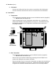
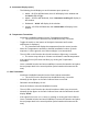


Jumper
Normal Position
Test Position
Diagram B
3. Wind Transmitter
- Insert two AA NiCad batteries (supplied) into the enclosed battery charger (be
sure to observe Polarity) and charge batteries for 12 hours.
o Note: Do not attempt to charge batteries other than NiCad batteries, as
they could explode, causing physical damage and/or fire.
- Feed the terminal lug end of the Yellow and Brown wires through one of the
rubber boots and connect the lugs to the terminals on the bottom of the wind
speed sensor using the brass nuts provided. The polarity does not matter.
o Note: Do Not adjust the nuts that are already on the sensor.
- Feed the terminal lug ends of the remaining 5 wires through the other rubber
boot and connect to the terminals on the bottom of the wind direction sensor
using the brass nuts provided.
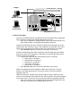
o Connect the 5 wires to the wind direction sensor as follows:
§ White wire to Terminal 1
§ Orange wire to Terminal 2
§ Black wire to Terminal 3
§ Red wire to Terminal 4
§ Green wire to Terminal 5
o Note: Do Not adjust the nuts that are already on the sensor.
- Slide the straight stub mast through the rubber boot and insert it into the
bottom of the wind speed sensor. Secure the sensor to the mast with the
supplied cotter pin.
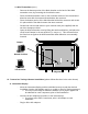
- Slide the formed (“Z” shaped) stub mast through the other rubber boot and
insert it into the bottom of the wind direction sensor with the #3 terminal aligned
over the mast arm. Secure the sensor to the mast with the supplied cotter pin.
o Note: If the sensor is not installed with the #3 terminal aligned over the
mast arm, wind direction readings will be incorrect.
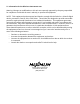
SIDE
COMPONENT
ES00057B