Summit Installation & Operation Instructions for remote operating mode 30 Samuel Barnet Blvd. New Bedford, MA 02745 (508) 995-2200 Fax (508) 998-5359 service.maximum@imtra.com www.maximum-inc.
Table of Contents Introduction................................................................................... 2 Preparing for Installation ............................................................ 2 What you need for the installation ........................................................................................................ 2 Planning the installation ....................................................................................................................... 2 Installation ..
Introduction Thank you for buying a Summit remote. These instructions are designed to take you step by step through the process of installing and using a Summit remote. Carefully following these instructions will help ensure many years of trouble free service from your installation. If you are uneasy about running wires you should consult a qualified professional. TV antenna, satellite dish, ham radio, home entertainment and alarm system installers are good choices.
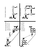
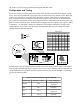
3 This example shows a setup where the current, high and low readings for the summit and base of the mountain are readable at both the summit and base of the mountain. Large Ski Area example This setup allows the current readings at the base and summit of the mountain to be read on indicators at both the base and summit.
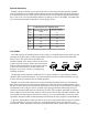
Remote Indicator(s) Summit’s large size allows it to be easily read from over 100 feet away when properly installed. For best performance you should avoid locations where direct sunlight will shine on the instrument. You must also have an AC outlet near the selected location. The AC adapter supplied with Summit has a 6 foot cord. You can extended this distance by splicing on wire to the adapter. The table below gives the maximum distances allowed for various gauges of wire.
sive than cables designed for noisy locations like factories. If you are using multiple remotes the cable length limits are for each segment of the daisy chain cabling. As an example, if you are using cable rated for 100 feet, then you can use 100 feet for each segment of the cabling for a total distance of 200 feet between the master and the second remote. If you need to have a data link of longer than a few hundred feet, you should use line extenders and/or short haul modems.
not do this as it will create a ground loop through the data link cable. Configuration and Testing We’re now ready to configure and test the system. First, the units of measurement jumpers need to be set. There are six standard PC type jumpers like you find on the circuit boards in a PC. When the jumper cap is mounted on the jumper pins, the jumper is closed, if the cap is not mounted on the pins, the jumper is open (see diagram).
Now it’s time to plug the terminal strips into the indicator. Note that there is a plug already installed in the space for the optional ice-free wind direction sensor, don’t remove this plug. To plug in a terminal, position it with the screw heads oriented toward the middle of the indicator and press into place firmly. The connectors will snap into place when inserted correctly.
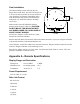
Final installation The indicator hangs on the wall from the two hanger holes on the back. The holes will accept #10 or #8 screws and are located on 16 inch centers for easy mounting (see diagram). Depending on the wall material you may need to use wall anchors, molly bolts, etc. Install the indicator mounting screws now. Make a hole in the wall behind the Indicator through which all wires will be fed. CAUTION: DO NOT MOUNT THE INDICATOR WITH ANY WIRES UNDER ITS LIP BECAUSE OF SHORT CIRCUIT HAZARD.
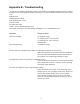
Appendix B - Troubleshooting If you have a problem with Summit, please try the following troubleshooting instructions to narrow down the source of the problem, before contacting us. If you need further assistance you may contact us at: Maximum Inc. 30 Samuel Barnet Blvd. New Bedford, MA 02745 (508) 995-2200 Fax (800) 989-2580 e-mail - service.maximum@imtra.com Also check our web site for late breaking information - www.maximum-inc.com Symptom Things to check LED’s do not light. AC Adapter wiring.
Appendix C - Common Questions and Answers Q A Q A Q A What are the two push button switches for? The two push button switches are only used with remotes that calculate Highs, Lows or Averages. They are used on the remotes for setting the time of the built-in clock. See the configuration and testing section for details. How do I test the clock battery? You can do this with a battery tester or you can simply set the time. Wait a few minutes then unplug the AC power.
• Connect the equipment into an outlet on a circuit different than from that which the receiver is connected. • Consult the dealer or an experienced radio TV technician for help. Shielded cables must be used with this unit to ensure compliance with the Class B FCC limits. If necessary the user should consult the dealer or an experienced radio/television technician for additional suggestions.
other warranty or liability in connection with its weather instruments. This warranty gives you specific legal rights and you may also have other rights which vary from state to state.