
Instruction Manual


18” WALL MOUNT
INSTALLATION
30 Samuel Barnet Blvd.
New Bedford, MA 02745
(508) 995-2200
Page 2
3b
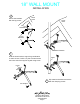
Bolt the remaining two half-sections together
with the support leg between to make one
complete bottom bracket assembly. The
support leg must be secured utilizing hole “B”
and oriented so that the bent flange will be
flush against the wall.
A
B
Must be oriented so that
flanged end will be flush
against the wall.
SUPPORT
LEG
ROOF
PEAK
1/8” PILOT
HOLES
18”
MINIMUM
LEVEL
14 1 2”
Drill two 1/8” level pilot holes 14 1 2” apart for each
bracket. Brackets must be separated from each
other by at least 18” for mast stability. Both
brackets must be aligned vertically for the mast
to be straight when installed.
5
Must be positioned
so that leg will utilize
hole “B”
BRACKET WILL
ACCOMMODATE
UP TO 18 INCHES
OVERHANG OF EAVE
MAST
ROOF
PEAK
4
Select a location that will be
high and free from any obstructions
to air flow for the sensors.
BOTTOM BRACKET ASSEMBLY