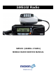
SM5102 Radio SM5102 (146MHz~174MHz) MOBILE RADIO SERVICE MANUAL
MaxonSM5102Radio 1.INTRODUCTION About Your SM5102 Radio Maxon's SM5102 mobile radio are Compatible. Conventional radio system operation. the SM5102 is capable of up to 208 channels 13 Groups per system in conventional operation. The operation and functions for the SM5102 radios are described in this manual. We urge you to thoroughly read this manual before operating the radio. Application of some functions described in this manual is determined by the system you use.
Maxon SM5102Radio This device complies with Part 15 of the FCC Rules. Operation is subject to the condition that this device does not cause harmful interference.
MaxonSM5102Radio WARNINGS 1. Components containing beryllium oxide are used in the equipment. Dust from this material is a health hazard if inhaled or allowed to come into contact with the skin. Great care must be taken when handling these components. They must not be broken or subjected to excessive heat. 2. Never operate the radio transmitter without the correct Maxon antenna, or a suitable artificial load, connected. 3.
Maxon SM5102Radio TABLE OF CONTENTS 1.SPECIFICATION 1.1 General 1.2 Transmitter 1.3 Receiver 2.MAINTENANCE & REPAIR 2.1 Introduction 2.1.1 Test Equipment Connection 2.1.2 Transmitter Performance Tests 2.1.3 Test Equipment Connection 2.1.4 Transmitter Performance Tests 2.1.5 Receiver Performance Tests 2.2 Alignment 2.2.1 Disassembly and Re-assembly of the Radio 2.2.2 PLL Alignment 2.2.3 Transmitter Alignment 2.2.4 Receiver Alignment 2.2.5 Receiver Performance Tests 3.DETAILED FUNCTIONAL DESCRIPTION 3.
MaxonSM5102Radio 1.1 General Performance Specifications FTZ 17TR2049 July 88 TIA-603 IEC 68 Series EC 529 IP54 MIL STD 810 C Band (Tx & Rx) (Switching range without retuning) VHF (V2) 146 – 174MHz Channel Spacing 12.5kHz, / 25kHz (programmable) (12.5, /25kHz switchable by CPU control) RF Output Power High Power Low Power Modulation Type F3E Audio Power 4W (Internal 16 Ω speaker) Intermediate Frequencies 45.1MHz First I.F., 455kHz Second I.F.
Maxon SM5102Radio Vibration BS2011 : Part 2.1Fc IEC 68-2-6 Part 2.1Fd IEC 68-2-34 Robustness Mil Std 810 C ESD 20kV (C-MIC = 15kV) EMC EMC Directive 89/336/EEC May 89 ETS 300.279 Physical Dimensions 175(W) x 158(D) x 48(H) mm Weight 1.44kgs Programmer SMP 6001 Reliability Analysis MTBF MTTR 15,000 Hours MIL-HDBK-217F. Ground benign. Parts stress method. 30 minutes average time to rework any SMD component and reassemble.
Maxon SM5102Radio 1.2 Transmitter 1.3 Receiver Test Method is ETS 300.086 2001 unless stated. Performance without Sub-Audio Modulation Test Method is ETS 300.086 2001 unless stated. Performance without Sub-Audio Modulation Power Output High Power Low Power Sensitivity 12dB SINAD UHF: Better than –117dBm 12dB SINAD VHF: Better than –118dBm 50W nominal 5W nominal Audio Freq. Deviation Nominal 12.5kHz +/-1.5kHz 20kHz +/-2.4kHz 25kHz +/-3.0kHz Amplitude Characteristic Peak +/-2.5kHz +/-4.0kHz +/-5.
Maxon SM5102Radio 2 MAINTENANCE & REPAIR 2.1 Introduction This section covers the tests which should be undertaken prior to handover of the radio to the end user. All of the following tests can be carried out without having to gain access to the interior of the radio. Recommended Test Equipment The alignment and performance test procedures assume the use of the following equipment. The functions of most of the equipment may be found in a “Communications Test Set”.
MaxonSM5102Radio Prerequisites For the following tests, signal generator modulation level should be set to Average System Deviation, i.e. 60% of maximum system deviation. 2.1.2 Transmitter Performance Tests Power Output a. Connect the transmitter to the Communications Test Set (CTS) with the power meter set to read 50W. The level should therefore be set to: 1.5 kHz for 12.5 kHz channel spacing 2.4 kHz for 20 kHz channel spacing 3.
Maxon SM5102Radio When CTCSS and DCS performance checks are also required, ensure that the lowest, middle and highest Rx/Tx frequencies include: Audio Output a. Set the RF signal generator to 1mV pd (-47.0dBm) and the tone and deviation as above. Lowest Rx/Tx freq. ch. 67.0 Hz CTCSS Middle Rx/Tx freq. ch. DCS Code 072 Highest Rx/Tx freq. ch. 250.3 Hz CTCSS b. Connect the audio power meter to the external speaker socket on the radio.
MaxonSM5102Radio 2.2 Alignment WARNINGS Any repairs or adjustments should only be made by, or under the supervision of, a qualified radio-telephone service technician. Replace the front panel by reversing the procedure. Rx VCO a. Select Channel 1. b. Check that the VCO tuning voltage at TP1 is >1.8V CAUTION c. This radio contains static sensitive devices.
Maxon SM5102Radio 2.2.2 Receiver Alignment The receiver is, by design, a broadband device. It should require no special alignment unless repairs are performed on the receiver. h. Adjust the RF level until the SINAD meter reads 10dB. The radio should unmute. This completes the receiver alignment process. The following alignment may be performed: a. Select Channel 1 on the radio. b. Set the RF generator to the receiver frequency and the RF level to 1mV pd (-47dBm). c. Set the AF signal to 1kHz. d.
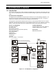
Maxon SM5102Radio 3 DETAILED FUNCTIONAL DESCRIPTION 3.1 VHF Transmit 1. Buffer 2. Power AMP 3. Low Pass Filter 4. Antenna Switch 5. A.P.C Circuits Buffer VCO output level is 0dBm and amplified to +17dBm (UHF)/(VHF). The buffer consists of Q2, 12,13 for isolation and gain. Power AMP The P.A Module(Q28) consists of 3-stage(Q18,Q39,Q28) amplifier and amplifies the TX signal from +37dBm to (+46~47)dBm. The input and the output terminal of the P.A Module are matcued 50 OHM.
MaxonSM5102Radio Level Shifter & Charge Pump The charge pump is used for changing output signals Fr, Fv at PLL IC from 0-5v to 16v necessary for controlling vco. DC to DC Converter The DC to DC converter converts the 8v to 15-16v to supply the necessary voltage for wide range frequency in vco. VCO The TX and RX VCO generates RF carrier and local frequency and each VCO is switched by a TX/RX power source.
Maxon SM5102Radio Power Amplifier and Harmonic Filter The power amplifier contains transistors Q12, Q13, Q18, Q39, Q28 and associated inductors, capacitors and resistors. When the radio is in transmit mode the diode D1,D15 is forward biased enabling the modulated RF signal from the VCO (amplified by the first stage amplifier / buffer Q12 and Q13) to pass to the pre-driver Q18 via Q39. The output signal is passed from Q39 to Q28 where it is then amplified for transmission.
MaxonSM5102Radio Receiver Audio and Sub-audio Circuit The receiver audio circuit has been fully controlled by Baseband Process, CMX881 supported by CML using internal software program. Frequency and CTCSS/DCS data storage EEPROM Rx/Tx channels, CTCSS/DCS as well as other data from the programmer are stored in the EEPROM. The data stored is retained without power supplied. This is a non-volatile memory. The EEPROM may have information re-programmed or erased.
Maxon SM5102Radio TCXO Set the channel selector to the mid-range frequency 455 MHz, adjust TCXO, for a reading of 445 MHz +/- 200Hz. For the UHF data radio, adjust the TCXO and set the frequency within the required range. APC 1. Adjust RV5 for fixing up High Power(50W) 2. Adjust RV1 for fixing up Low Power(5W) 3.
MaxonSM5102Radio 1. Features ■ Wideband frequency separation ■ 9 character display with icons ■ 2 or 25W Programmable output power ■ Programmable 12.5 /25 KHz Channel Spacing ■ Programmable function keypad ■ Channel Scan ■ Priority Channel Scan ■ Look Back Channel ■ CTCSS/DCS/DTMF tone signaling ■ Bush Channel Lock out ■ Marked idle ■ Time out timer ■ Public Address ■ Two Tone ■ SMS ■ DTMF ■ Scan List Edit ■ Priority Channel Edit ■ Programmable On/Off HOOK function 2.
Maxon SM5102Radio 3. BASIC Operation ■ Function keys There will be six push-buttons on the face of the SM5102; Up, Down, P1, P2, P3 and Emergency. below are the default programming settings. ■ Up button/ Down key - This button will allow the operator to scroll up/down through the available channel. A press-and-release of this button will increase/decrease the channel number. A press-and-hold will scroll through the succeeding channel num.
MaxonSM5102Radio ■ Emergency KEY – When emergency button is pushed, an emergency signal is automatically transmitted for the specified time period. This is where the DTMF tone to be transmitted as the Emergency Call can be entered. After the emergency call, the transceiver performs transmission and reception alternately with the following conditions: - Transmits the microphone signals - Receives the signal and emits audio When Press the PTT, the function is cancelled.
Maxon SM5102Radio 2.Adding or Deleting to P Scan List If each Channel is included in P Scan Editable List, Channel Number would display P scan Icon. To add or delete channel from P Scan Editable List, use P2 button. ■ Programming When the SM-2000/5000 Series is powered from the programming interface, the MCU checks PC-program Enable port. If the PC-program enable port is active status, the MCU enters programming Mode. The LCD display” ProGram” 1. Reading SM-2000 / 5000 assumes PC is ready to receive data.
MaxonSM5102Radio ■ Squelch Options The Radio supports 3 kinds of Squelch Options. Different Squelch option can be applied to each channel. 1. CTCSS 38 kinds of TIA/EIA Standard CTCSS Tones can be set up. All tones can be set up using PC Programmer. - TX Operation: If PTT key is pressed, the Radio occurs CTCSS tone, which is programmed to each channel and goes TX mode. Tone would occur during TX. - TX close: When TX mode closes, the Squelch Tail Elimination of the radio would work.
Maxon SM5102Radio ■ Normal Scan Any number of channels shall be entered into the scan list. This will be equal to or less than the number of programmed channels. The LED shall flash green if programmed to. The flashing green LED will stop when ‘CARRIER’, or ‘CARRIER AND CORRECT TONE’. During scan delay, the LED shall remain clear. When Scan Delay expires and Scan Speed resumes, the LED shall also resume flashing green. ■ Priority Scan A priority channel can be programmed at the initial radio set-up stage.
MaxonSM5102Radio ○ 2 Push the appropriate [0]-[9], A,B,C,D,*,# to enter the desired character. ○ 3 Push the CLR Key. Number or character will be deleted at last Number or character. ○ 4 Push and hold the CLR key. All messages will be deleted. the radio enter the standby mode. ○ 5 Push the RCL key. Press the number key. DTMF message which is stored number is displayed at LCD. ○ 6 Push the RCL Key. Press the #,* key to removed the displayed data from the LCD. the radio enter the standby mode.
Maxon SM5102Radio ○ 4 . Push and hold the ACC-703 [STR ] button to enter the message scroll mode. ○ 5 . Push the ACC-703 [#],[ * ] button to scroll the messages. ○ 6 . Push [SMS] : again to return to the standby condition 3. Transmitting an SMS - 9 SMS memory channels are available and the messages can be edited via PC Programming and ACC703. 3.1 SMS Transmission 3.1.1 Using SMS memory by PC Programming ○ 1 Push [SMS] to enter the SMS code memory channel selection mode.
MaxonSM5102Radio 5. FUNCTION Display 1 2 3 P 4 5 6 7 L 8 9 ֠ 1 Signal strength indicator : Indicates relative signal strength level 2 TX Indicator :Appears while transmitting 3 Scan Indicator : Appears at the scan Channel 4 P Scan Indicator : Appears at the Priority scan Channel 5 Key Lock Indicator : Appears during the key lock function is on. 6 Speaker Indicator : Appears when the monitor mode 7 Low Power Indicator : Appears when low output power is selected.
Maxon SM5102Radio 6. PC Programmer ■ Computer Pentium II processor or faster (recommended) ■ Operating System Microsoft Windows® 98, 2000, NT, XP 7.
MaxonSM5102Radio 4 TROUBLE SHOOTING GUIDE SYMPTOMS Unit does not Work Warning tone& No Work Bad RX Sensitivity (-10 to -60dB) Defective RX PLL Error NO TX Power CAUSES 1. Complete discharge of battery (13.8V+/-10%) 2. Regulator 3. 5v voltage source COUNTERMEASURES 1. Replace battery. 2. Replace regulator(U20) 3. IC1.Q20 (5v+/-0.2v) 1. Pll error 2. Filtering Error 3. EEPROM Fail 1. Check U1.Y2.U6 2. Check LPF 3. Re-programming 4. Replace or charge battery 1. 2. 3. 4. 5. 6. 1. Check D1.2.15 2.
Maxon SM5102Radio BASE DIAGRAM BASE DIAGRAM MANUFACTURER’S PART NUMBER REFERENCE NO. KTC5084 KTC3880 Q202.203.302.303 AT-41532 Q601 KTC4075 Q41.42.43.44.46 KTA2014 Q602.641.643 PBR951 Q12 BFR92A .Q3.2.13 KTC3875S Q901.904.7 KTA1504S Q902.903 KRC104S (ND) KRC101SNA KRC404V KRA104S (PD) KRA304V] KRA310V KRA226 SYMBOL Q5.6.8.10.16 .19.22.26.27.30.32 34.37.38.48 Q9 KRC110S (NK) BASE DIAGRAM KRA110S (PK) KRA101S KRA104 Q1.4.11.29.31.33. 36.40.204.
MaxonSM5102Radio ZENER (5.6V) D23.22.5 HSMS-2817 D911 1SV229 1SV217 MMBV109 HVU300ATRU 1SS314 KDS121V KDS160 KDS114 D201.202.301 D701.901.921 D10 SM4004 UPP9401 D.2..15 KTA1663 Q722 Q23 SI4412DY BFG35 BLT50 XRC5640C.
Maxon SM5102Radio FX828D5 MT8870D CMX881 HD6473837UX U13.34 Codec IC MCU U18 KIA324F MB15E03SL TA31136FN Voltage Detector IC PLL IC U1 IF IC U2 NJM12903V Comparator NJM12904V OP AMP MC14053BD IC406 MC14066BD MAX232 U3 MUX./DEMUX. Analog S/W IC DBL5020V KIA324F OP AMP COMPANDER NJM12904V CAT25C32/64 LM386M TDA7233D KIA358 JRC2073 KIA358 LM358 AD5300 MSNBLPS OP-AMP U6 IC203 U4.5.9.11.12. 15.16.
MaxonSM5102Radio TK71750SCL TK71733SCL TK71730CL TC7S66FU KTX301E KRX201U KRC824E 2SK3475 1(Gate) 2(Source) 3(Drain) IC1.U22 VOLTAGE REGULATOR IC Q101 Q103 Q107.
Maxon SM5102Radio KTB1367 1(BASE) 2(COLLECTOR) 3(EMITTER) U20.Q14 PNP Transistor Q23.