
User's Manual
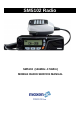

MaxonSM5102Radio
Prerequisites
For the following tests, signal generator
modulation level should be set to Average
System Deviation, i.e. 60% of maximum
system deviation.
The level should therefore be set to:
1.5 kHz for 12.5 kHz channel spacing
2.4 kHz for 20 kHz channel spacing
3.0 kHz for 25 kHz channel spacing
If the radio has had components installed to
change the channel spacing and/or operating
band from those installed at the factory,
ensure that the correct components are
installed in the receiver and transmitter
stages prior to testing.
Refer to the appropriate Electrical Parts List if
necessary.
EEPROM programming
Ensure that the EEPROM has the required
customer parameters programmed,
otherwise ensure that a test EEPROM is
programmed with at least the lowest, middle
and highest Rx/Tx frequencies prior to
aligning the VHF and UHF scanning
handheld series radio.
When CTCSS and DCS performance checks
are also required, ensure that the lowest,
middle and highest Rx/Tx frequencies
include:
Lowest Rx/Tx freq. ch. 67.0 Hz CTCSS
Middle Rx/Tx freq. ch. DCS Code 072
Highest Rx/Tx freq. ch. 250.3 Hz CTCSS
The middle Rx/Tx frequencies should be
halfway between the lowest and the highest
frequencies.
Programming details are given in Section 7.
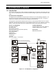
2.1.1 Test Equipment Connection
Connect the power supply leads from the
battery eliminator to the power supply. The
red, positive, lead connects to +13.8Vdc.
The black, negative, lead connects to the
negative, terminal of the power supply.
2.1.2 Transmitter Performance Tests
Power Output
a. Connect the transmitter to the
Communications Test Set (CTS) with
the power meter set to read 50W.
b. Set the power supply to 13.8Vdc and
connect a dc voltmeter across the
power supply to monitor the supply
voltage.
c. Set the CTS to the same frequency as
the radio and PTT. Check and record
the power output. The nominal power
output is 5W for low power and 50W for
high power.
d. Reduce the power supply voltage to
11Vdc and PTT. The output power
should be greater than 65% of the level
measured above.
Frequency Error
a. Using the frequency counter check that
the transmit frequency is within
+/- 500Hz (VHF) or +/- 750Hz (UHF) of
the frequency which is programmed
into the radio.
Spot Deviation and Distortion
a. Set the radio to the middle Tx
frequency. Connect the oscilloscope to
the output of the modulation meter.
b. Set the audio signal generator to 1kHz
tone, low output impedance and
adjust its level for 60% system
deviation:
12.5kHz channel spacing 1.5kHz dev.
20kHz channel spacing 2.4kHz dev.
25kHz channel spacing 3kHz dev.
c. Press PTT.
d. Measure the audio distortion. This
should be less than 5%.
e. Increase the audio signal generator
level by 20dB (10x voltage). The peak
deviation should be:
12.5kHz channel spacing <= 2.25kHz dev.
20kHz channel spacing <= 3.6kHz dev.
25kHz channel spacing <= 4.5kHz dev.
f. Release PTT.