SP200/210 Service Manual
Published by Maxon Electronics Ltd 36a Gibson Avenue Padstow Sydney NSW Australia 2211 Tel: +61 (0) 2 9707 2000 Fax: +61 (0) 2 9707 3328 e-mail sales@maxon.com.au Internet: www.maxon.com.au Any queries regarding information in this manual, please contact the Technical Services Group Leader at the above address. Information provided in this document is believed correct at time of printing but is subject to change without notice.
SM-SP200/210 Maxon SP200/210 Radio AMENDMENT RECORD SHEET All amendments to this manual should be incorporated as soon as they are received and recorded below: Issue No. Effective Date Reason for Change Date Signature All Engineering Bulletins relevant to this product should be placed at the rear of this binder. Please ensure that this manual is updated with any replacement pages, which may accompany these Engineering Bulletins.
Maxon SP200/210 Radio SP200/210 WARNINGS • Components containing beryllium oxide are used in the equipment. Dust from this material is a health hazard if inhaled or allowed to come into contact with the skin. Great care must be taken when handling these components. They must not be broken or subjected to excessive heat. • Never operate the radio transmitter without the correct Maxon antenna, or a suitable artificial load, connected.
SP200/210 TABLE OF CONTENTS 1 INTRODUCTION 1.1 1.2 1.3 2 SPECIFICATIONS 2.1 3 5 General ACCESSORIES & OPTIONS 3.1 3.2 3.3 4 Using this Manual Amendments to this Manual Contact Information Pre-Install Check Accessories Options INSTALLATION, COMMISSIONING & ALIGNMENT 1-1 1-1 1-1 1-2 2-1 2-1 3-1 3-1 3-1 3-1 4-1 4-1 4-1 4-2 4-6 4-6 4-6 4-7 4-8 4-8 4-9 4-10 4-11 4-11 4-14 DETAILED FUNCTIONAL DESCRIPTION 5-1 TROUBLESHOOTING 6.1 Diagnostic Function 6.2 Troubleshooting Chart 6.3 Voltage Charts 6.
Maxon SP200/210 Radio 8 EXPLODED MECHANICAL DRAWINGS & PARTS LISTS 8.1 Parts List 8.2 Spare Parts 8.3 Mechanical Parts 8.4 SL100 VHF Parts List 8.4.1 V2 Control Circuit 8.4.2 V2 RF 8.4.3 TCXO Assembly 8.4.4 V2 VCO 8.4.5 V2 Front End 8.5 SL100 UHF Parts List 8.5.1 U2 Control Circuit 8.5.2 U2 RF 8.5.3 TCXO 8.5.4 VCO 9 CIRCUIT DIAGRAMS & PCB LAYOUTS 10 SPARE PARTS 10.1 Spare Parts 10.1.1 Component Replacement 11 APPENDIX – ACC-2003 ALIGNMENT BOX 11.1 Purpose 11.2 Test Equipment 11.
SP200/210 Maxon SP200/210 Radio Figure 6-1 – Legend Layout for Top Side of Digital PCB ............................................................................... 6-5 Figure 6-2 - Legend Layout for Bottom Side of Digital PCB ........................................................................... 6-6 Figure 6-3 - Legend Layout for Top Side of RF PCB ..................................................................................... 6-7 Figure 6-4 - Legend Layout for Bottom Side of RF PCB ........
Maxon SP200/210 Radio WARNINGS Page vi SP200/210 Issue 1.
SP200/210 Maxon SP200/210 Radio 1 INTRODUCTION This Maxon Service Manual is a comprehensive guide to the maintenance and field repair of this equipment. It covers a number of versions of the SP200/210 radio and its accessories. Differences between the versions are indicated, as appropriate, in the text. Before using this manual please read the whole of this introductory chapter, this will help you to make the best use of it.
Maxon SP200/210 Radio SP200/210 Category definitions are: ‘A’ Category A Engineering Bulletins will only be released if, by using the equipment manufactured by Maxon or its subcontractors, a risk to operator safety or an infringement of Type Approval is probable. All units affected should be returned for modification to Maxon Europe Works Department on receipt of such a Bulletin. ‘B’ Category B Engineering Bulletins are for equipment manufactured by Maxon that may have component batch problems.
SP200/210 Maxon SP200/210 Radio 2 SPECIFICATIONS 2.1 General Performance Specifications R&TTE Appendix IV CE 168 ETS 300.086 Jan 91 I-ETS 300 219 Oct 93 ETS 300 279 Feb 96 TIA/EIA-603 Band VHF UHF Channel Spacing 12.5kHz or 25kHz Channel spacing is programmable. RF Output Power 1W / 5W (programmable and variable) Modulation Type G3E Audio Power 1W (Internal 4 Ω speaker) 500mW (External 8Ω speaker), Intermediate Frequencies 45.1MHz First I.F., 455kHz Second I.F.
Maxon SP200/210 Radio SP200/210 Environmental Operating Temperature Range Storage Temperature Range -15 to +35°C (nominal) -20 to +55°C (extreme), -40 to +80°C (storage) Charging Temperature Range 0 to +30°C Humidity EIA/TIA 603 (95%) Protection against ingress of dust and water IEC 529 IP54 Vibration BS2011 : Part 2.1Fc IEC 68-2-6 Part 2.
SP200/210 Maxon SP200/210 Radio 3 ACCESSORIES & OPTIONS 3.1 Pre-Install Check The SP200/210, as purchased, is supplied with an Antenna, charger and power supply, belt clip and User Manual. 3.2 Accessories A wide range of accessories are available for the SP200/210. The list below represents a summary of accessories available at the time this manual was published. For up-to-date listings, and for price and availability, please refer to the current Price Book.
Maxon SP200/210 Radio ACCESSORIES & OPTIONS Page 3-2 SP200/210 Issue 1.
SP200/210 Maxon SP200/210 Radio 4 INSTALLATION, COMMISSIONING & ALIGNMENT 4.1 Installation The SP200/210 is a hand-held radio and thus requires no installation. The User should ensure that the batteries are charged before commencing commissioning tests. 4.2 Connections 1. Antenna connector: socket. 2. Channel Busy / Talk tri-colour LED. 3. Display 5 4. Main Power switch and volume control. Fully anti-clockwise is the OFF position. BACK 5. Battery Release Catch. 6. Speaker. 7.
Maxon SP200/210 Radio SP200/210 The Accessory connector is wired as follows: PTT / Mic Ground Speaker Figure 4-2 – Connections The small multi-pin connector, which is connected to the other end of the test lead, is wired as follows: PTT / Mic Screen 1 2 6 View from 5 rear of connector 3 4 Speaker Figure 4-3 - Hirose connector 4.3 Commissioning This section covers the tests, which should be undertaken prior to handover of the radio to the end user.
SP200/210 Maxon SP200/210 Radio Commissioning Equipment 2 1 3 5 4 Figure 4-5 – Commissioning Kit Note: For those dealers who already have the SK2055 Service Kit (SL25/55) the audio cable (2), CA8700, may be purchased. This interfaces the Service Kit to the SP200/210 and allows all simple, commissioning audio measurements to be made. SMA adapter (5), ME210089 will also be required. Flexi-pcb (3), ME110016 may be required if simple internal adjustments are to be made.
Maxon SP200/210 Radio SP200/210 Discrete Test Equipment RF Signal Generator (with CTCSS/1kHz tone) RF Power Meter RF Frequency Counter Spectrum Analyser and notch filter (optional) Audio Signal Generator Audio Power Meter SINAD Meter Modulation Meter Oscilloscope Voltmeter DC Power Supply, 0 - 10V 3A min. Combined Equipment Communications Test Set (e.g. Marconi TF2955, Stabilock 4015 or similar). Accessories ME210089 SMA to BNC Adapter.
SP200/210 Maxon SP200/210 Radio SK 3100 Service Kit 1 2 4 3 Figure 4-8 - SK 3100 Service Kit This kit can be used for commissioning in the same way as the SK2055 (ignoring computer connections). The above kit also includes a battery eliminator. Note: If the Interface Box is used, ensure that it is set to manual, Audio enable is off and PTT is off before powering up. If programming the radio with the Battery eliminator connected, the curly cord must be disconnected from the Interface Box.
Maxon SP200/210 Radio EEPROM programming Ensure that the radio has the required customer parameters programmed, otherwise ensure that the radio is programmed with at least the lowest, middle and highest Rx/Tx frequencies prior to aligning the VHF and UHF scanning handheld series radio. Ensure that High and Low power are programmed. When CTCSS and DCS performance checks are also required, ensure that the lowest, middle and highest Rx/Tx frequencies include: Lowest Rx/Tx freq. ch. 67.
SP200/210 g. Check that the signal generator RF level is < -117dBm (UHF) or < -118dBm (VHF). Squelch a. Ensure that both the radio and the Test Set are set to the appropriate channel spacing. Maxon SP200/210 Radio This section is included here as it is not necessary to disassemble the radio in order to set the power output. A stable power source is required and therefore the ACC-2003 Interface Box should be used as this contains a battery eliminator. For squelch adjustments, see Section 4.5.6. b.
Maxon SP200/210 Radio SP200/210 4.5 Alignment CAUTION This radio contains static sensitive devices. Static safe precautions should be observed, in particular we would recommend the use of a suitable floor mat, table mat, bonding cords and a wrist strap. The soldering iron should have an earthed tip. Tests without Disassembly Power Output, Deviation, Balance and Squelch adjustment do not require the radio to be disassembled.
SP200/210 Maxon SP200/210 Radio 4.5.2 Disassembly and Re-assembly of the Radio 1 Radio In order to carry out the following PLL and Alignment procedures it will be necessary to gain access to the inside of the radio. Care should be exercised when opening up the radio for maintenance or repair. REMOVING AND REPLACING THE BATTERY Removal Holding the radio chassis in one hand, press and hold the battery release catch (1) on the top of the battery pack.
Maxon SP200/210 Radio REMOVING AND REPLACING THE MAIN ASSEMBLY Removal With the battery pack removed, there are four, black, cross-head screws visible. These can now be removed along with the black, cross head screw holding the accessories socket dust cover. SP200/210 LOCATION OF ADJUSTMENT POINTS Unscrew the antenna and slide off the volume control knob. Replace the battery but do not push all of the way home.
SP200/210 Rx VCO a. Select Channel 1. b. Check that the VCO tuning voltage at TP1 is >5.7V +/- 0.25V (VHF) or >1.0V +/- 0.25V (UHF). c. Select Channel 3 d. Check that the voltage at TP1 is <12.5V. Tx VCO a. Select Channel 1. b. Set the PTT switch to on and check that the voltage at TP1 is 1.0V +/- 0.25V (VHF) or 2.0V +/- 0.25V (UHF). c. Maxon SP200/210 Radio 4.5.4 Squelch Sensitivity The RF input level to open the squelch is usually set in the range –123.5 to –117dBm (0.15 to 0.3mV).
Maxon SP200/210 Radio SP20/210 All further adjustments require the use of the ACC-2003 Alignment Box. Refer to the ACC-2003 User Manual (on floppy disk) for operational information. OSCILLOSCOPE RADIOCOMMUNICATIONS TEST SET SERIAL DATA DEMOD AF IN AF OUT AUDIO AUDIO IN Power ATE ACC-2003 INTERFACE BOX ATE TXD AUDIO RXD PTT Power AUDIO OUT DC POWER SUPPLY SERIAL DATA 7.5VDC @ 2.4A max.
SP200/210 Maxon SP200/210 Radio Balance Adjustment a. Select Channel 3 (using software). If necessary, adjust TXTRIM1 to keep within the system deviation. b. Set the audio generator to a 310Hz tone, low output impedance, at a level of 400mV. h. Press Shift + R to return to receive. c. Press Shift + T on the keyboard to transmit. d. Adjust TXTRIM2/TXTRIM3 to give a square wave on the oscilloscope (check that audio enable is ON on the Interface Box. CTCSS / DCS deviation a. Select Channel 4. b.
Maxon SP200/210 Radio SP200/210 This completes the transmitter alignment process. 4.5.6 Receiver Alignment Audio Volume Level a. Set the test set to the appropriate frequency at –47dBm with 1kHz tone modulation at 60% system deviation: 12.5kHz channel spacing 1.5kHz dev. or 20kHz channel spacing2.4kHz dev. or 25kHz channel spacing3kHz dev. b. Select Channel 1. c. With the calibration program running on the PC, select Rx_Vol. d. Turn the volume control to maximum. e.
SP200/210 Maxon SP200/210 Radio 5 DETAILED FUNCTIONAL DESCRIPTION 5.1 Introduction This section provides a detailed description of the operation of the radio. 5.2 Common Circuits Power Circuits Battery voltage, or external voltage through the accessories connector, is applied via a 4A fuse (plus diode protection) directly to the RF power module and, after the on/off switch, to the dc to dc converter and voltage regulator. The majority of the circuitry is powered via IC1, which regulates the +7.
Maxon SP200/210 Radio SP200/210 5.3 Audio ASIC The audio ASIC (IC406) processes both the audio signal and the sub-audible tones, including filtering, amplifying, setting attenuations levels etc. It is a programmable device, controlled by the microcontroller, hence alteration of deviation levels is achieved by the ACC-2003 Alignment Software. The internal block diagram is shown in Figure 5-1. The audio and SAT routes within the ASIC will be described separately. 5.3.
SP200/210 Maxon SP200/210 Radio 5.3.2 Sat Signal Path ASW4 VSCLPF SATRIM1 SATRIM2 COM ASW4 switches between RxSAT (RDIN) and Tx SAT (TXIN) and routes to the filter. Seventh order Elliptic Variable Switched Capacitor Low Pass Filter. Cut-off frequency is variable from 50Hz to 300Hz. Level adjustable in 0.5dB steps from –3dB to +2.5dB. Output is on pin 23 FLT OUT. Not used. SAT level adjustment. Amplitude is controlled in 0.5dB steps from – 3dB to +2.5dB. Output is on pin 23 FLTOUT.
Maxon SP200/210 Radio SP200/210 5.4 Audio/SAT Circuits CTCSS / DCS Decoder Circuits Discriminator audio from pin 9 IC5 is applied, via IC408D, to pin 3 of the audio ASIC. The audio th frequencies of the signal are filterecd out by the 7 order Elliptic Low Pass Filter, leaving only the SAT audio tones. The level is then set by the ASIC and is routed via IC407A back to the ASIC for comparison with a reference voltage. This produces the logic data signal.
SP200/210 Maxon SP200/210 Radio Battery Low Indicator Circuit When the battery voltage drops below 5.6 VDC a Battery Low indication is given. Due to the volts drop across D403, a voltage below 5.6V on the battery gives a voltage less than 5V on the base of Q405. , Q405 switches on its when base is below 5v (current flow through R413), which switches on Q404, so driving pin 52 of the microcontroller low (normally tied high).
Maxon SP200/210 Radio SP200/210 In transmit the VCO has modulation from the audio processing circuitry applied to D202. C204 is used to provide compensation for non-linearity caused by the modulation diode and maintains a constant modulation regardless of the frequency of operation. PLL IC The reference frequency from the TCXO, at 12.8 MHz, is connected to pin 20 of IC2 (MC145191). The appropriate VCO is connected to pin 11.
SP200/210 Maxon SP200/210 Radio 5.6 Transmitter The transmitter comprises: Figure 5-3 - Transmitter Block Diagram Buffer The RF output level from the VCO is 0dBm. This is amplified to +17dBm by the buffer amplifier consisting of Q16, Q17, Q3 and associated components. All stages are simple common-emitter amplifiers with resistive biasing and tuned collectors. A pi-type attenuator (R31, 32 and 34) is used between the two stages. PA module The PA module consists of a hybrid amplifier.
Maxon SP200/210 Radio SP200/210 5.7 Receiver The receiver comprises: Rx VCO Local Oscillator ~ ~ Audio Filter Audio Amplifier FM LimiterDiscriminator Squelch Circuit Figure 5-4 - Receiver Block Diagram Antenna Switch In receive, the diodes D5 and D6 are reverse biased. L13 is now in circuit, passing the signal from the antenna to the front end without signal loss. Front End The receive signal is routed to the RF Front End module, pin 1.
SP200/210 Maxon SP200/210 Radio First Mixer D9, T1 and T2 form a double balanced mixer which provides the 45.1MHz intermediate frequency output. The filtered frequency from the front end module is coupled to T1. The Local oscillator input from the VCO is coupled to T2. The output of the mixer is taken from the tap on transformer T1 and fed to the single pole diplexer, comprising L15 / C93 and R65 (High-pass terminating filter) and L14 / C92 (Low-pass coupling filter) The 45.
Maxon SP200/210 Radio SP200/210 Noise detector circuit The noise detector circuit, in conjunction with IC5, consists of transistors Q26, Q27, thermistor TH1 and diode D11. Any noise signal present is applied to Q27 from pin 11 of IC5. The signal is amplified by Q27, rectified by D11 and then buffered by Q26. The buffered signal is applied to pin 12 of IC5 (Squelch input). The squelch trigger output (pin 14, IC5) is applied to the microcontroller BUSY input on pin 54 of IC403.
SP200/210 Maxon SP200/210 Radio 6 TROUBLESHOOTING This section includes voltage and troubleshooting charts which should assist the engineer to isolate and repair the fault. Voltage measurements should be made using a high-impedance voltmeter and the values given are with respect to ground. Obvious checks, such as battery performance on load, should be made before pulling the radio apart. Substitution of another set of batteries, or the use of a power supply, isolates this cause.
Maxon SP200/210 Radio SP200/210 6.2 Troubleshooting Chart Symptoms Radio does not work Warning Tone and radio does not work Poor Rx sensitivity (-10 to –60dBm) Defective Rx PLL Error Low / No Tx power No modulation No programming Causes 1. Battery is discharged (below 6V =/-10%) 2. Fuse blown 3. 5V supply missing 1. PLL error 2. EEPROM failure 3. Low battery 1. 2. 3. 4. 5. 6. 1. 2. 1. 2. 3. 1.
SP200/210 Maxon SP200/210 Radio 6.3 Voltage Charts The following voltages have been measured on a VHF radio. The Control Circuit, Main Circuit and Integrated Circuit voltages apply to the UHF radio as well. 6.3.1 Transistors (Main Circuit) Ref. No. Q5 Q6 Q7 Q10 Q11 Q12 Q13 Q14 Q15 Q16 Q17 Q18 Q19 Q20 Q21 Q22 Q23 Q24 Q25 Q26 Q30 B 0 4.0 5 0.5 3.0 5 14 0.5 4.0 0 3.0 0 4.0 0 4.0 4.5 4.0 0 4.5 0 4.0 Rx C 0 0.7 0 0 4.0 0 14 0 4.0 3.0 0 4.0 0 4 4.0 0 0.7 4.5 0.7 0.7 0 E 0 1.5 0 0 0 0 14 0 0 4.0 0 4.0 4.
Maxon SP200/210 Radio SP200/210 6.3.2 Integrated Circuits Receive Pin 1 2 3 4 5 6 7 8 9 10 11 12 13 14 15 16 17 18 19 20 IC1 3.5 3 3.5 3.6 3.3 3.3 3.3 3.7 0 0.8 1 0 3.5 0 0 1.8 IC3 1.8 AUDIO 4 AUDIO AUDIO GND GND GND 0.5 0.5 4.5 0 2.5 2.5 IC4 1.9 0 1.9 1.9 1.9 5 1.9 A CLK 0 5 0 1.9 1.9 IC5 GND GND GND 4.5 GND 6 IC6 1.2 1.4 1.6 1.5 0 0 0 0 4 0 2.5 4.5 0 4 AUDIO 4.5 IC9 1.6M 4.5 4.5 4.5 4.5 0 0 0 4.5 2 2 4.5 3 4.5 0 0 4.5 0 0 2 IC11 1 GND 0 GND AUDIO 6 3 1 IC12 0 0 0 0 GND 4.5 4.5 4.
SP200/210 Maxon SP200/210 Radio COMPONENT LOCATION – Top Side of Digital pcb Figure 6-1 – Legend Layout for Top Side of Digital PCB Issue 1.
Maxon SP200/210 Radio SP200/210 COMPONENT LOCATION - Bottom side of Digital pcb Figure 6-2 - Legend Layout for Bottom Side of Digital PCB TROUBLESHOOTING Page 6-6 Issue 1.
SP200/210 Maxon SP200/210 Radio COMPONENT LOCATION – Top side of RF pcb Figure 6-3 - Legend Layout for Top Side of RF PCB Issue 1.
Maxon SP200/210 Radio SP200/210 COMPONENT LOCATION – Bottom side of RF pcb Figure 6-4 - Legend Layout for Bottom Side of RF PCB TROUBLESHOOTING Page 6-8 Issue 1.
SP200/210 Maxon SP200/210 Radio 7 PROGRAMMING 7.1 SMP6100 7.1.1 Introduction The SMP6100 allows programming of the SP200/210 radio and enables you to: 1. Program frequencies and built-in signalling operations. 2. Customise radios to your own requirements. 7.1.3 Programming Having entered the SMP6100 programmer you are greeted with the front screen. Select the appropriate product. SP200 (American Version) SL100 (European Version) Select the appropriate band.
Maxon SP200/210 Radio the same way except that a digital burst is used instead of any audio tone. Select one of the tone options for receive operation and press Select Features Menu Having accessed the Personality Programmer Screen and entered your radio’s data, press the right arrow key to access the Select Features Menu. To disable power save mode, press when in RX delay time. (Selection of the left arrow key or will redisplay the previous menu.
SP200/210 Maxon SP200/210 Radio Having pressed , the following subwindow is displayed: Enter record information if desired to end If you wish to assign some text to the file (i.e. a description of the data type etc.), type it now and press The following screen prompt is then displayed at the bottom of the screen: Type a serial number if you want to retrieve this data by serial no. Enter Radio Serial No.
Maxon SP200/200 Radio PROGRAMMING Page 7-4 SP200/210 Issue 1.
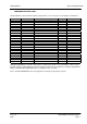
SP200/210 Maxon SP200/210 Radio 8 EXPLODED MECHANICAL DRAWINGS & PARTS LISTS 8.1 Parts List The following pages detail the mechanical and electronic parts for the Maxon SL100 radio. Refer to the following two pages for the exploded diagram. When using the Parts List, you will notice that each part number has been allocated a category: A, B or C. The definitions of these categories are as follows: A= An item which is manufactured by Maxon Korea and can be ordered as a stock item.
Maxon SP200/210 Radio Category B B B B B Code & Part No. 895-754 895-763 906-706 906-929 937-498 SP200/210 Description O-ring Con O-ring Felt Insulation Plate (speaker) Owner’s Manual Item No. 15 SL100U2 Category A A A A A A A Code & Part No.
SP200/210 Maxon SP200/210 Radio Please note that this section details the complete parts list of the radio. This information is provided for information only and does not imply that these parts are available as spares. Please note the category designation, as described above. For details on servicing, please refer to Section 10. 8.3 Mechanical Parts Figure 8-1 - Exploded Mechanical Drawing 1 Issue 1.
Maxon SP200/210 Radio SP200/210 No. 1 2 3 4 5 6 7 8 9 10 11 12 13 14 15 16 Part No.
SP200/210 Maxon SP200/210 Radio Figure 8-2 - Exploded Mechanical Drawing 2 No. 25 26 27 28 29 30 31 32 33 34 35 36 Part No. 406-767-A 252-107-1 436-046-5 251-234-7 612-081 772-462 221-324-6 772-427 406-787-A 651-156 772-429 406-785-A Issue 1.0 03/01 Part Name PCB LCD LED Display Sw TACT LED Chip (+) Machine Screw (BH) Shield Can Power Module Shield Can (Front End) PCB Front End NUT Shield Can (TCXO) PCB TCXO Description 20.6 x 15 x 1.
Maxon SP200/210 Radio 37 38 39 40 41 42 43 44 66 67 71 72 73 74 75 772-428 406-764-B 416-096-A 422-930-0 753-049 906-542 895-549 895-763 895-753 895-754 895-661 600-804 906-939 895-685 895-660 772-496 772-497 SP200/210 Shield Can (VCO) PCB VCO PCB RF Spring Coil Terminal Insulation Plate Terminal Gasket Ring Gasket Volume Control O Ring Antenna Control O Ring Cushion Plastic Screw (Mic) Double Sided Tape Cushion Cushion Shield Shield NSP T0.2 21 x 18 x 0.8 FR4 1/1 99 x 53.3 x 1.
SP200/210 No. 45 46 47 48 49 50 51 52 53 54 55 56 57 58 59 60 61 62 63 64 65 68 70 73 Part No. 719-656 421-197-0 959-046-B 95A-177-A 95A-670 719-657 752-958 906-858 752-808 753-061 406-766-A 906-857 753-037 719-659 732-975 611-388 826-395 881-656 826-396 853-170 612-306 895-686 895-452 895-660 Issue 1.0 03/01 Maxon SP200/210 Radio Part Name Cover Back Connector ANT Label Name Label FCC No.
Maxon SP200/210 Radio SP200/210 8.4 SL100 VHF Parts List 8.4.1 V2 Control Circuit Category C Code & Part No.
SP200/210 Category C C C C C C C C C C C Maxon SP200/210 Radio Code & Part No.
Maxon SP200/210 Radio Category C C C Code & Part No. 421-203-2 422-470-1 436-046-5 SP200/210 Description CONNECTOR DF15(6.2)-30DP-0.65V(51) CONNECTOR WAFER 53048-0410 1.25W/B SW TACT SKPT-1101VA Qty 1 1 3 Location CON404 CON401 SW402.403.4 05 Code & Part No.
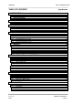
SP200/210 Category Maxon SP200/210 Radio Code & Part No. Description Qty Location C C C C C C C C C C C 05C-104-6Z 05C-683-2Z 06F-108-3 060-153-3Z 060-203-5Z 075-102-5 075-103-6 098-333-8 101-058-9 130-A17-6Y 130-A60-4Y CHIP RESISTOR 100K 1/16W 1% T 1608 CHIP RESISTOR 68K 1/16W 1% T 1608 CHIP RESISTOR 0.1 1W 1% 1218 CHIP RESISTOR 15K 1/10W 5% T 2012 CHIP RESISTOR 20K 1/10W 5% T 2012 RES.CHIP TRIMMER 1K RH03E1C13X RES.
Maxon SP200/210 Radio Category C C C SP200/210 Code & Part No.
SP200/210 Category C C C C C C C C C C C Maxon SP200/210 Radio Code & Part No. 311-069-4 311-077-1 311-079-3 311-170-1 311-297-3 311-298-4 311-323-3 416-096-C 421-204-3 422-930-0 450-528-0 Description COIL CHIP 0.15UH:NL252018T-R15J COIL CHIP 0.68UH:NL252018T-R68J COIL CHIP 1.0UH:NL252018T-1R0J COIL CHIP 1000UH:300SS-102K=CP3 COIL SPRING 3X0.55X5T:L SMD COIL SPRING 3X0.55X4T:L SMD COIL SPRING 2.8X0.4X8T:L P.C.B RF 99 X53.3 X1.0 FR4 2/S CONNECTOR DF15(0.8)-30DS-0.
Maxon SP200/210 Radio SP200/210 8.4.4 V2 VCO Category C C C C C C C C C C C C C C C C C C C C C C C C C C C C C C Code & Part No. 05B-101-3Z 05B-103-5Z 05B-104-6Z 05B-201-0Z 05B-222-9Z 05B-472-8Z 05B-473-9Z 060-104-9Z 130-A75-8Y Description CHIP RESISTOR 100 1/16W 5% T 1608 CHIP RESISTOR 10K 1/16W 5% T 1608 CHIP RESISTOR 100K 1/16W 5% T 1608 CHIP RESISTOR 200 1/16W 5% T 1608 CHIP RESISTOR 2.2K 1/16W 5% T 1608 CHIP RESISTOR 4.
SP200/210 Maxon SP200/210 Radio 8.5 SL100 UHF Parts List 8.5.1 U2 Control Circuit Category C Issue 1.0 03/01 Code & Part No.
Maxon SP200/210 Radio Category SP200/210 Code & Part No.
SP200/210 Maxon SP200/210 Radio 8.5.2 U2 RF Category Issue 1.0 03/01 Code & Part No. 05B-000-5Z Description CHIP RESISTOR 0 Qty 3 Location R124.LK3.D9 03 05B-100-2Z 05B-101-3Z CHIP RESISTOR 10 1/16W 5% T 1608 CHIP RESISTOR 100 1/16W 5% T 1608 2 7 R79.908 R11.15.28.66. 88.97.130 05B-102-4Z 05B-103-5Z CHIP RESISTOR 1K 1/16W 5% T 1608 CHIP RESISTOR 10K 1/16W 5% T 1608 4 8 R54.71.86.94 R1.53.82.98.1 03.104.106.
Maxon SP200/210 Radio Category SP200/210 Code & Part No. 05B-911-8Z Description CHIP RESISTOR 910 1/16W 5% 1608 05C-104-6Z 05C-683-2Z 06F-108-3 060-153-3Z 060-243-1Z 075-102-5 075-103-6 098-333-8 101-058-9 130-A17-6Y CHIP RESISTOR 100K 1/16W 1% T 1608 CHIP RESISTOR 68K 1/16W 1% T 1608 CHIP RESISTOR 0.1 1W 1% 1218 CHIP RESISTOR 15K 1/10W 5% T 2012 CHIP RESISTOR 24K 1/10W 5% T 2012 RES.CHIP TRIMMER K RH03E1C13X RES.
SP200/210 Category C Issue 1.0 03/01 Maxon SP200/210 Radio Code & Part No. 132-266-4Y 132-714-2Y 133-349-1Y 133-350-1Y 134-012-1Y 134-757-1Y Description CHIP CERAMIC CHIP CERAMIC CHIP CERAMIC CHIP CERAMIC CHIP CERAMIC CHIP CERAMIC 2.2PF GRM40 COG2R2C 50V P 27PF GRM40 COG270J 50V P 33PF GRM39 COG330J 50V P 330PF GRM39 COG331J 50V P 4PF GRM39 COG040C 50V P 47PF GRM39 COG470J 50V P Qty 1 1 2 1 1 4 134-761-4Y 134-767-0Y 134-770-2Y CHIP CERAMIC 470PF GRM40 COG471J 50V P CHIP CERAMIC 4.
Maxon SP200/210 Radio Category Code & Part No. 270-109-9 270-314-7 270-316-9 271-165-4 280-110-2 300-223-8 310-659-2 310-859-6 311-069-4 311-077-1 311-078-2 311-079-3 311-167-9 311-170-1 311-301-3 416-096-C 420-417-8 421-204-3 422-930-0 450-528-0 SP200/210 Description FILTER CERAMIC CFWM455F DISCRIMINATOR CDBC455CX16-TC FILTER CERAMIC LTWM455HT CRYSTAL FILTER 45Y15BN 45.1MHZ FUSE 60 V 4 A 25NM-040-L REEL:SM TRANSFORMERS CHIP 617PT-1019 COIL CHIP 10UH:LER015T100K COIL CHIP 18NH:LL2012-F18NM COIL CHIP 0.
SP200/210 Maxon SP200/210 Radio 8.5.4 VCO Issue 1.0 03/01 05B-101-3Z CHIP RESISTOR 100 1/16W 5% T 1608 1 R202 05B-103-5Z CHIP RESISTOR 10K 1/16W 5% T 1608 1 R201 05B-104-6Z 05B-183-7Z CHIP RESISTOR 100K 1/16W 5% T 1608 CHIP RESISTOR 18K 1/16W 5% T 1608 1 1 R203 R205 05B-221-8Z 05B-222-9Z 05B-472-8Z 05B-473-9Z 130-A75-8Y 130-515-9Y 130-704-3Y 131-092-8Y 131-563-7Y 132-260-8Y CHIP RESISTOR 220 1/16W 5% T 1608 CHIP RESISTOR 2.2K 1/16W 5% T 1608 CHIP RESISTOR 4.
Maxon SP200/210 Radio EXPLODED MECHANICAL DRAWINGS & PARTS LISTS Page 8-22 SP200/210 Issue 1.
SP200/210 Maxon SP200/210 Radio 9 CIRCUIT DIAGRAMS & PCB LAYOUTS The following Circuit Schematics and PCB Layouts are included: P416097 P416096c P406787a P406764c P496785a Digital PCB RF PCB Front End VCO TCXO Larger circuit diagrams are available to order, if required. This Service Manual and the circuit diagrams are available to Dealers / Distributors on the Maxon Intranet Web Site. Issue 1.
Maxon SP200/210 Radio CIRCUIT DIAGRAMS & PCB LAYOUTS Page 9-2 SP200/210 Issue 1.
SP200/210 Maxon SP200/210 Radio P416097c Digital Board Top Figure 9-1 – Digital Board Layout Top Side Issue 1.
Maxon SP200/210 Radio SP200/210 P416097c Digital Board Bottom Figure 9-2 - Digital Board Layout Bottom Side CIRCUIT DIAGRAMS & PCB LAYOUTS Page 9-4 Issue 1.
SP200/210 Maxon SP200/210 Radio P416096c RF PCB Top (V2) Figure 9-3 - RF Board Layout Top Side Issue 1.
Maxon SP200/210 Radio SP200/210 P416096c RF PCB Bottom Side (V2) Figure 9-4 - RF Board Layout Bottom Side P406787a Front End CIRCUIT DIAGRAMS & PCB LAYOUTS Page 9-6 Issue 1.
SP200/210 Maxon SP200/210 Radio Figure 9-5 – Front-End Board Layout P406764c VCO PCB Figure 9-6 – VCO Board Layout Issue 1.
Maxon SP200/210 Radio SP200/210 P496785a TCXO PCB Figure 9-7 – TCXO Board Layout CIRCUIT DIAGRAMS & PCB LAYOUTS Page 9-8 Issue 1.
SP200/210 Maxon SP200/210 Radio 10 SPARE PARTS 10.1 Spare Parts The following items only are held as replacement parts for the SL100. Category A A A A A A A A A A A A A A A B B B B B B B B B B B B B B B B B B B B B B B B B B B B B B B B B B Code & Part No.
Maxon SP200/210 Radio 10.1.1 Component Replacement Surface mount components Surface mount components should always be replaced using a temperature controlled soldering system. The soldering tools may be either a temperature controlled soldering iron or a temperature controlled hot-air soldering station. A hot-air system is recommended for the removal of components on the multi-layered boards used in the radio.
SP200/210 Maxon SP200/210 Radio Surface mounted integrated circuit replacement Soldering and de-soldering techniques of the surface mounted IC’s are similar to the above outlined procedures for the surface mounted chip components. Use extreme care and observe static precautions when removing or replacing the defective (or suspect) IC’s. This will prevent any damage to the printed circuit board or the surrounding circuitry. The hot-air soldering system is the best method of replacing surface mount IC’s.
Maxon SP200/210 Radio 10. SPARE PARTS & MAINTENANCE POLICY Page 10-4 SP200/210 Issue 1.
SP200/210 Maxon SP200/210 Radio 11 APPENDIX – ACC-2003 ALIGNMENT BOX 11.1 Purpose This Section is reproduced from the ACC-2003 User Guide and provides information on the operation of the ACC-2003 Interface Test Jig. This jig is used for the Service adjustment of the SP200/210 radio. The Calibration program (Calibration.exe) is used to allow the setting of ASIC conditions within the radio. Default ASIC conditions can be programmed into a radio and then repeated from radio to radio.
Maxon SP200/210 Radio SP200/210 Select the required band and press Enter. Figure 11-2 will be displayed. Figure 11-2 - Calibration Program Primary Screen To dedicate the Communication Port, select Configuration and enter the relevant port number. Selecting EEPROM loading will retrieve the current ASIC values, stored in the radio. This is used for the alignment of the radio. This selection should not be made if the EEPROM is empty (new EEPROM) or if the radio is in the middle of another operation.
SP200/210 Maxon SP200/210 Radio If writing is in progress, ASIC CONTROL will be displayed, see Figure 11-3. See Section 11.4 for default ASIC values; these may alter depending upon Production requirements. Figure 11-3 - ASIC Control Screen (Rx) Issue 1.
Maxon SP200/210 Radio SP200/210 11.3.2 Adjustment of ASIC values With the ASIC Control screen open, use the TAB key on the PC keyboard to tab along until the required parameter is highlighted. Note; Only parameters within the Rx or Tx mode can be accessed. Once the required parameter is highlighted, make adjustments using the PgUp and PgDn keys on the PC keyboard.
SP200/210 Maxon SP200/210 Radio INTRIM Adjusts the Mic audio in 0.5dB steps from -4dB to +3.5dB. SATRIM1 Adjust the signal amplitude of DTMF in 0.5dB step from 0dB to 7.5dB For the receiver the following parameters can be adjusted (see Figure 11-5): Figure 11-5 - ASIC Control Screen (Rx) INTRIM Adjusts the demodulated audio at IF IC in 0.5dB steps from -4dB to +3.5dB. SATRIM2 Adjusts the SAT tone received level in 0.5dB steps from +12 to +13.5dB.
Maxon SP200/210 Radio SP200/210 11.3.3 Transmit Adjustments The transmit mode is entered by pressing SHIFT + T on the keyboard. Ensure that the Power Supply is set to +7.5V. 11.3.3.1 Power Adjustment The power level is set by the potentiometers on the back plate of the radio, they are located underneath the Type Approval label. Note: A spare label is shipped with every radio. Refer to the Service Manual for the correct procedure for setting the power levels.
SP200/210 Maxon SP200/210 Radio 11.3.4 Receive Adjustments The receive mode is entered by pressing SHIFT + R on the keyboard. Ensure that the power supply is set to +7.5V. 11.3.4.1 Audio Output Level Set Test Set RF level to –47dBm, with 1kHz audio modulation at 20dB above nominal. Set the volume control to maximum and adjust RX_VOL to generate 2.2Vrms audio output level. Any other adjustments are covered earlier on in this Service Manual. Issue 1.
Maxon SP200/210 Radio SP200/210 11.4 Default Settings 11.4.1 V1 Band Default Settings CH RX 1ch 2ch 3ch 4ch 5ch 6ch 7ch 8ch 9ch 10ch 11ch 12ch 13ch 14ch 15ch 16ch 17ch 18ch 19ch 20ch 21ch 22ch OPTION TX 136.025MHz No 136.075MHz 138.025MHz No 138.075MHz 145.025MHz No 145.075MHz 150.025MHz No 150.075MHz 160.025MHz No 160.075MHz 136.025MHz No 136.075MHz 138.025MHz No 138.075MHz 145.025MHz No 145.075MHz 150.025MHz No 150.075MHz 160.025MHz No 160.075MHz 145.025MHz 67Hz(CTCSS) 145.075MHz 145.
SP200/210 Maxon SP200/210 Radio 11.4.2 V2 Band Default Settings CH RX OPTION TX OPTION N/S POWER 1ch 2ch 3ch 4ch 5ch 6ch 7ch 8ch 9ch 10ch 11ch 12ch 13ch 14ch 15ch 16ch 17ch 18ch 19ch 20ch 21ch 22ch 146.025MHz 155.025MHz 160.025MHz 168.025MHz 173.025MHz 146.025MHz 155.025MHz 160.025MHz 168.025MHz 173.025MHz 155.025MHz 155.025MHz 155.025MHz 155.025MHz 155.025MHz 155.025MHz 155.025MHz 155.025MHz 155.025MHz 155.025MHz 155.025MHz 155.025MHz No No No No No No No No No No 67Hz(CTCSS) 100Hz 250.
Maxon SP200/210 Radio SP200/210 11.4.3 U1 Band Default Settings CH 1ch 2ch 3ch 4ch 5ch 6ch 7ch 8ch 9ch 10ch 11ch 12ch 13ch 14ch 15ch 16ch 17ch 18ch 19ch 20ch 21ch 22ch RX 400.025MHz 410.025MHz 415.025MHz 420.025MHz 429.025MHz 400.025MHz 410.025MHz 415.025MHz 420.025MHz 429.025MHz 415.025MHz 415.025MHz 415.025MHz 415.025MHz 415.025MHz 415.025MHz 415.025MHz 415.025MHz 415.025MHz 415.025MHz 415.025MHz 415.025MHz OPTION No No No No No No No No No No 67Hz(CTCSS) 100Hz 250.3Hz 67Hz 100Hz 250.
SP200/210 Maxon SP200/210 Radio 11.4.4 U2 Band Default Settings CH 1ch 2ch 3ch 4ch 5ch 6ch 7ch 8ch 9ch 10ch 11ch 12ch 13ch 14ch 15ch 16ch 17ch 18ch 19ch 20ch 21ch 22ch RX 440.025MHz 450.025MHz 455.025MHz 460.025MHz 469.025MHz 440.025MHz 450.025MHz 455.025MHz 460.025MHz 469.025MHz 455.025MHz 455.025MHz 455.025MHz 455.025MHz 455.025MHz 455.025MHz 455.025MHz 455.025MHz 455.025MHz 455.025MHz 455.025MHz 455.025MHz OPTION No No No No No No No No No No 67Hz(CTCSS) 100Hz 250.3Hz 67Hz 100Hz 250.