
Specifications

A Remote Automated Water Quality Stream Gauging System Design 13
13
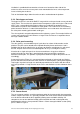
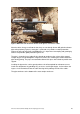
A length of light 15 mm steel pipe is attached to the stand to protect the cables in the event
of fire. Steel pipe is also used to run the cables up the platform leg for fire resistance. The
pipe terminates below ground level where it is connected to the cable conduit.
The cables at the platform are protected using 16 mm corrugated conduit which terminates at
a gland in the bottom of the electronics enclosure.
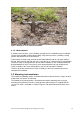
3.6. Power system
The power system consists of a solar panel array, deep cycle batteries and solar regulator.
Cabling from the solar panel(s) is routed through 16 mm corrugated conduit down the solar
panel mounting pole and into the sampler enclosure. For the 12 V system the cable is
terminated at the solar regulator which is mounted on the inside of the sampler enclosure
behind the false wall. A 50 mm gland installed in the return of the false back panel allows
cable access to the batteries which are located in the front section of the sampler enclosure.
A 24 VDC circuit is created by duplicating the 12 VDC system and connecting the two
batteries in series using a common ground.
All system components are wired directly to the battery terminals. Most solar regulators offer
a 12 V power output however the switching noise generated by the operation of the regulator
can lead to noise in analogue measurements. Direct connection to the battery prevents this
noise and ensures that power is available to all components even in the event of a regulator
failure.
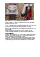
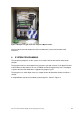
3.7. Electronics enclosure and wiring
All electronic components housed within the enclosure are attached to the removal backing
plate. Components are positioned to allow easy access and adequate air flow. Relays, fuses
and terminal blocks are attached to the backing plate using DIN rail. The closed venting
system for the pressure transducer is also mounted in this way.
Cabling is routed to the box through a 50 mm gland that is connected to the auto sampler
housing. The gland is sealed using a mastic compound to remove any entry points for
insects. The cables are then routed through trunking to their final destination.
A wiring diagram is shown in Appendix 3 - Wiring Diagram.
The antenna cable for the modem is not routed through the auto sampler enclosure and
therefore enters the logger enclosure through a separate 16 mm gland.