Extended AT Commands Manual VERSION 2.1 FW V 2.1.3 This document is the sole and exclusive property of Maxon Australia. Not to be distributed or divulged without prior written agreement. 36A Gibson Ave Padstow NSW 2211 Australia URL: www.maxon.com.
RF EXPOSURE COMPLIANCE The use of this device in any other type of host configuration may not comply with the RF exposure requirements and should be avoided. During operation, a 20 cm separation distance should be maintained between the antenna, whether extended or retracted, and the user’s/bystander’s body (excluding hands, wrists, feet, and ankles) to ensure RF exposure compliance. CAUTION Change or modification without the express consent of Maxon Electronics Australia Pty. Ltd.
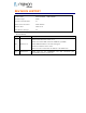
REVISION HISTORY Product Name Maxon ModMax - MM-6280IND Document Type Public Current Version Number 2.1 Status of the Document Public Release Revision Date 2009-03-20 Total Number of Pages 68 - Revision History Level Date History Released with Firmware version 2.1.3 Added Auto Delete SMS command AT$$AUTO_DLTSMS 2.0 2008-05-18 Added SMSOPT=AB if set sms notif is skipped New Reset command with 2 states. Maxon.rssi now returns ECIO in addition to the RSSI value. 2.
CONTACT INFORMATION Depending on the nature of your inquiry, please feel free to contact the following senior personnel: Sales, Marketing & Corporate: Technical Support: Phone: Sales: Phone: +61 2 8707 3000 Email: support@maxon.com.au +61 2 8707 3000 Email: sales@maxon.com.
TABLE OF CONTENTS Extended AT Commands Manual ............................................................................................... 1 RF EXPOSURE COMPLIANCE .................................................................................................... 2 CAUTION ........................................................................................................................................ 2 REVISION HISTORY ..............................................................................
5.4. Visual/Audible Call Alert Options........................................................................................24 5.4.1.1. Receiving notification mode option (AT$$RCV_MODE))..........................................24 5.4.1.2. Ringer volume control (AT$$RINGLVL)..................................................................24 5.4.1.3. Ringer melody selection (AT$$RINGIDX) ...............................................................24 5.5. 6. Network Relational Settings.........
9. 8.1.1.18. Write Message to Memory +CMGW........................................................................42 8.1.1.19. Delete Message +CMGD ........................................................................................43 8.1.1.20. Send Command +CMGC .......................................................................................43 8.1.1.21. More Messages to Send +CMMS............................................................................44 8.1.1.22.
14. CELLULAR EXTENDED AT COMMAND SET .....................................................................66 14.1.1. Cellular AT parameter commands .............................................................................66 14.1.2. Cellular identification AT command extensions .........................................................67 14.1.3. Cellular result codes for Asynchronous data services ................................................68 15. DM COMMAND (DIAGNOSTIC MODE) .................
1. OVERVIEW The modem is a rugged, full duplex Data and SMS modem designed to operate on 3G 850MHz networks. 3G is an efficient and secure cellular wireless technology that compliments fixed or mobile applications. The modem incorporates RS-232 and USB drivers, AC/DC down converter. The modem connects directly to a HOST computer utilizing a RS-232C or USB V1.1 interface. The Host signals are converted to the RS-232C or USB 1.1 signal levels.
1.2. Terms The following terms are used throughout this document. We have provided and explanation of these for your reference. Table 1-1 Term Description <> Field. Contents between ‘<’ and ‘>’ indicate the name of the field or the parameter required to complete the syntax. Delimiter/Space. Insert a space. AT command set Communications command set interface between data terminal equipment (DTE) and data circuit terminating equipment (DCE). BS Base Station.
Term Description PSTN Public Switched Telephone Network refers primarily to the telephone system based on copper wires carrying voice, fax & data. RCE Remote Customer Equipment. Describes the MT2, Rm and TE2 as one composite system. Rm Hardwire Interface between MT2 and TE2. SMS Short text Message Service. TE2 Terminal Equipment 2. A TE2 is a data terminal device that has a nonISDN user-network interface, e.g., CCITT V series or CCITT X series. Same as DTE.
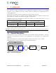
2. AT INTERFACE DESCRIPTION 2.1. Basic Integration The modem supports asynchronous serial communication known as RS-232. This chapter describes the basic integration and communication of MT2 with TE2. MT2 hereby defines and TE2 means host products which can issue AT commands and handle the response through UART or RS-232 signalling. The popular examples of TE2 are PC’s, PDA’s and unmanned systems such as Data Loggers, RTU’s or PLC’s. 2.2.
2.3. Command Format The AT command set in UART1 is based on ASCII text. The extended AT command set by Qualcomm start with “AT$QC” and the extended AT command set by Maxon Australia start with “AT$$”. All commands should finish by , 0x0d. Other formats and rules in the AT command set keep to IS-707A. Any spaces in the AT command field are ignored and the space in the parameter field should be removed if it is not necessary unless otherwise specified.
3. BASIC INTERFACE CONFIGURATION 3.1. Baud Rate Set-up This section provides basic information on setting the data communication rate [baud rate] on the Rm interface between MT2 and TE2. 3.2. Serial Interface The default transfer rate is set to 115200bps with support to 230400bps. On the RS232 Serial connection. NOTE: changes to +IPR rate are written to default NV memory in F0 profile independent of the &W command. Use &W command to write +IPR changes to F1-5 user profiles. 3.3.
Special: Set command Command TE2 Æ MT2 $$Connect_Baud= $$ Connect_Baud = (OK | ERROR) Response TE2 Å MT2 1: Modem displays baud rate set by +IPR command together with Connect message after a circuit switched connection is established. E.g. If IPR is set to 19200, the connect message should display Connect 19200. 0: Displays only connect message. In this case the modem only display Connect after a circuit switched connection is established. 3.4.
Command TE2 Æ MT2 $$NOTIFCNT? 0: No notification (No boot alert message, No SMS message notification. Notifies of incoming data calls.) Value 1: No boot alert message on start-up but notifies when SMS message is received. Notifies of incoming data calls 2: Notify Once (default) Boot up alert message on start-up and notifies when SMS message is received.
4. SIGNAL INFORMATION 4.1. MT SMS Table 4-10 Status Signal Action AT SMS Notification to Serial and USB ports $$SMSNOTIF value “0”: No alert Idle, Data $$SMSNOTIF value “1”: Buzzer alerts 4 times initially only Buzzer $$SMSNOTIF value “2”: Buzzer alerts 4 times initially followed by once every two sec. $$SMSNOTIF value “3”: Buzzer alerts 4 times initially only 4.2.
5. INTERFACE ENVIRONMENT 5.1. MT2 Basic Operational State. This command set enables the user to set up and/or confirm MT2’s basic operational environment. 5.1.1.1. Boot alert After power up MT2 notifies TE2 it is active on the network and in idle state by this command.
Table 5-14 Read command Command TE2 Æ MT2 $$EMMOREG? Response TE2 Å MT2 $$EMMOREG: period,terminatednumber,TI,msg period: 5 – 300 (seconds) Value terminatednumber: mobile number TI: Teleservice Identifier (4098) msg: User data Table 5-15 Set command Command TE2 Æ MT2 $$EMMOREG= Command TE2 Æ MT2 $$EMMOREG=CANCEL (Disable command expected by MT2) Response TE2 Å MT2 $$EMMOREG: 1 | 0 (Success | Failure) 5.1.1.4.
Command TE2 Æ MT2 $$RESET Response TE2 Å MT2 $$RESET: 1 | 0 (Success | Failure) Note: Using the new format with the old firmware R1.1.17 will cause the modem to hang. For older firmware (R1.1.17 please use AT$$RESET=n where n is in minutes) 5.1.1.6. Current time (AT$$TIME) This command enables the user to view the current date, time and day. Table 5-20 Read command Command TE2 Æ MT2 $$TIME Response TE2 Å MT2 $$TIME: Value 5.1.1.7.
Extended AT Commands Manual Page 21 of 70 2009-06-25
5.2.1.2. LED control (AT$$EXT_LED) This command is used for control of the LED’s on-time. Changes made to this function are written to NV memory and will be present in all profiles. Table 5-24 Read command Command TE2 Æ MT2 $$EXT_LED? Response TE2 Å MT2 $$EXT_LED: Value Time: 0~255 seconds (0: Continuous LED ON - Default) Table 5-25 Set command Command TE2 Æ MT2 Response TE2 Å MT2 5.2.1.3.
5.3.1.1. SMS low battery voltage set point (AT$$LOWBATT_VTG) This command also sets the SMS Auto Voltage Alert value. (For remote user SMS notification activation please see SMS Auto Voltage Alert). Table 5-28 Read command Command TE2 Æ MT2 $$LOWBATT_VTG? Response TE2 Å MT2 $$LOWBATT_VTG: 610: Default – voltage point set for $$LOWBATT 1 notification xxxx: 4 digit number representing voltage to 2 decimal points x100 (i.e. 12.
5.4. Visual/Audible Call Alert Options 5.4.1.1. Receiving notification mode option (AT$$RCV_MODE)) This command is used for selecting preferred mode of incoming call alert. Table 5-32 Read command Command TE2 Æ MT2 $$RCVMODE? Response TE2 Å MT2 $$RCV_MODE: 0: LED with Ring (Default) Value 1: LED only 2: Ring Only Table 5-33 Set command Command TE2 Æ MT2 $$RCV_MODE= Response TE2 Å MT2 $$RCV_MODE: 1 | 0 (Success | Failure) 5.4.1.2.
Command TE2 Æ MT2 $$RINGIDX= Response TE2 Å MT2 (OK | ERROR) 5.5. Network Relational Settings 5.5.1.1. Roaming indicator information (AT$$ROAMIND) This command is used for reading Roaming Indicator Information. Table 5-38 Read command Command TE2 Æ MT2 $$ROAMIND Response TE2 Å MT2 $$ROAMIND: 0: Not Roaming Value 1: Roaming inside preferred roaming list 2: Roaming outside preferred roaming list 5.5.1.2.
5.5.1.4. Modem scheduled Information (AT$$Ping) Scheduled information will include Antenna Signal, EC\Io, Time, RSCP Level and Location Example output: RSSI[79], TIME[2007-07-18,08:20:21,WED], ECIO:-13 ,RSCP[-71], L0151 R01 CI1CA5 SRB0---Read command Command TE2 Æ MT2 $$PING? Response TE2 Å MT2 $$PING: Value 1~43200: Notification every seconds. The modem sends a notification continuously (at set interval). The notification should include RSSI, Time, EC\Io, RSCP and location.
Command TE2 Æ MT2 $$CURRSTATE -1: Offline 0: Idle state 1: Initialisation state Value 2: Alert state 3:Conversation state 4: Access state 5: Paging state 5.5.1.7. RF information (AT$$RFINFO) This command enables user to acquire RF information between MT2 and the on-air system. MT2 transmits the following messages according to an argument status between MT2 and the on-air system.
6. DIAGNOSTIC COMMANDS These commands are used for testing and diagnostic purposes. They can not be used in the calling state. 6.1.1.1. Ring test (AT$$DIAG_RING) This command is used to confirm MT2 ring alert function. Table 6-47 Execute Command Command TE2 Æ MT2 $$DIAG_RING= Response TE2 Å MT2 $$DIAG_RING: 1 | 0 (Success | Failure) Value 6.1.1.2. 1 – 20000 Ringing time in sec 0: stop test LED test (AT$$DIAG_LED) NOTE: This function incorporates a soft power reset.
Command TE2 Æ MT2 $$RSSI_LEVEL? Default settings in –dBm units: Value Upper: 95 (-dBm) Stronger Lower: 120 (-dBm) Weaker Table 6-50 Set Command Command TE2 Æ MT2 $$RSSI_LEVEL=, Response TE2 Å MT2 $$RSSI_LEVEL: , Upper: 20 ~ 100 (-dBm) Value Lower: 50 ~ 120 (-dBm) E: upper_value must be a lower number than the lower_value 6.1.2. Led Description Power: On when modem has power and signal is above or better than -95dbm.
7. DATA CALL SET-UP The following tables describe MO data call procedures. Call released or failed (Uses DTR pin) Table 7.51 Notification command Notify TE2 Å MT2 NO CARRIER 7.1. Data Calls SIM Card with Data Number enabled (Contact Telstra and ask to activate Code 2620 on the SIM account) 7.1.1.1. MO data call Table 7.52 Command TE2 Æ MT2 Command TE2 Æ MT2 ATD CONNECT (Data call connected) Notify TE2 Å MT2 Connect if connect_baud is set.
8. SMS commands 8.1.1. General Configuration Commands 8.1.1.1. Select Message Service +CSMS Set command selects messaging service . It returns the types of messages supported by the ME: for mobile terminated messages, for mobile originated messages and for broadcast type messages. If chosen service is not supported by the ME (but is supported by the TA), final result code +CMS ERROR: shall be returned.
Table 24. +CPMS action command syntax Command +CPMS=[, [,]] Possible response(s) +CPMS: ,,,,, +CMS ERROR: +CPMS: ,,,,,, +CPMS? +CPMS=? 8.1.1.3. ,, +CMS ERROR: +CPMS: (list of supported s),(list of supported s), (list of supported s) Message Format +CMGF Set command tells the TA, which input and output format of messages to use.
304 305 310 311 312 313 314 315 316 317 318 320 321 322 330 331 332 340 500 …511 512… 8.1.1.5. invalid PDU mode parameter invalid text mode parameter (U)SIM not inserted (U)SIM PIN required PH-(U)SIM PIN required (U)SIM failure (U)SIM busy (U)SIM wrong (U)SIM PUK required (U)SIM PIN2 required (U)SIM PUK2 required memory failure invalid memory index memory full SMSC address unknown no network service network timeout no +CNMA acknowledgement expected unknown error other values in range 256...
same commands, but only when the length of the SMSC address coded into parameter equals zero Table 5. +CSCA action command syntax Command Possible response(s) +CSCA=[,[tosca>] +CSCA +CSCA=? 8.1.1.7. +CSCA: , Set Text Mode Parameters +CSMP Set command is used to select values for additional parameters needed when SM is sent to the network or placed in a storage when text format message mode is selected.
8.1.1.9. Informative Examples In this example, the volatile parameter settings of TA are used to construct messages in text mode. SMSC address setting is used also in PDU mode AT+CRES (restore settings from non-volatile memory to volatile memory) OK AT+CSMP?;+CSCA? (query SM parameters) +CSMP: 17,167,0,0 (default values for SMS-SUBMIT) +CSCA: "+358501234567",145 (SMSC address) OK Message Receiving and Reading commands 8.1.1.10.
and replaced with the new received indications. 1 Discard indication and reject new received message unsolicited result codes when TA-TE link is reserved (e.g. in on-line data mode). Otherwise forward them directly to the TE. 2 Buffer unsolicited result codes in the TA when TA-TE link is reserved (e.g. in online data mode) and flush them to the TE after reservation. Otherwise forward them directly to the TE. 3 Forward unsolicited result codes directly to the TE.
0 No CBM indications are routed to the TE. 1 If CBM is stored into ME/TA, indication of the memory location is routed to the TE using unsolicited result code: +CBMI: , 2 New CBMs are routed directly to the TE using unsolicited result code: +CBM: (PDU mode enabled); or +CBM: ,,,, (text mode enabled) If ME supports data coding groups which define special routing also for messages other than class 3 (e.g.
NOTE: If the selected can contain different types of SMs (e.g. SMS-DELIVERs, SMS-SUBMITs, SMS-STATUS-REPORTs and SMS-COMMANDs), the response may be a mix of the responses of different SM types. TE application can recognize the response format by examining the third response parameter. Table 9.
,,[], ,,] if text mode (+CMGF=1), command successful and SMS-STATUSREPORT: +CMGR: ,,,[],[],,- , if text mode (+CMGF=1), command successful and SMS-COMMAND: +CMGR: ,,[,,[],[],[], ] if text mode (+CMGF=1), command successful and CBM storage: +CMGR: ,,,,, otherwise: +CMS ERROR: +CMGR=? 8.1.1.13.
8.1.1.14.
error, final result code +CMS ERROR: is returned. See chapter Message Service Failure Result Code for a list of values. This command should be abortable. - entered text (3GPP TS 23.040 TP-Data-Unit) is sent to address and all current settings (refer Set Text Mode Parameters +CSMP and Service Centre Address +CSCA) are used to construct the actual PDU in ME/TA.
message upon unsolicited delivery status report result code. If sending fails in a network or an ME error, final result code +CMS ERROR: is returned. See chapter Message Service Failure Result Code for a list of values. This command should be abortable. Table 13. +CMSS action command syntax Command +CMSS=[,[,< toda>]] Possible response(s) if text mode (+CMGF=1) and sending successful: +CMSS: [,] if sending fails: +CMS ERROR: +CMSS=? 8.1.1.17.
[,] [,] AT+CMGW="phone number",,"REC UNREAD","callback "timestamp" AT+CMGW="phone number",,"REC READ","callback number","timestamp" number", text is entered +CMGW=? 8.1.1.19. Delete Message +CMGD Execution command deletes message from preferred message storage location . If is present and not set to 0 then the ME shall ignore and follow the rules for shown below.
Command Possible response(s) if text mode (+CMGF=1): +CMGC=,[,[,[,[ ,]]]] text is entered if text mode (+CMGF=1) and sending successful: +CMGC: [,] if sending fails: +CMS ERROR: +CMGC=? 8.1.1.21. More Messages to Send +CMMS Set command controls the continuity of SMS relay protocol link. When feature is enabled (and supported by network) multiple messages can be sent much faster as link is kept open.
Storing an unsent message in memory, sending it from there, and deleting it: AT+CPMS? (check memory settings) +CPMS: "ME",4,10,"ME",4,10,"ME",4,10 OK AT+CMGW="9501231234" (write message) > This is the message body^Z +CMGW: 7 (index number in storage returned) OK AT+CMSS=7 (send from storage) +CMSS: 12 (success: reference value 12 sent from SC) OK AT+CMGD=7 (delete message) OK Extended AT Commands Manual Page 45 of 70 2009-06-25
9. SMS Processing Options 9.1.1. SMS Send and Receive Options 9.1.1.1. SMS Mail Notification Option (SMSOPT=AB) A value is set to skip SMS notification message Notify TE2 Response TE2 Å MT2 Å MT2 Message (message only) $$SMSOPT=AB Value 9.1.1.2.
9.1.1.3. SMS Mail Notification Option (SMSOPT=1) Received SMS:
9.1.2. Auto delete Messages in ME Memory 9.1.2.1. Auto Delete Messages in ME memory($$AUTO_DLTSMS) Table 9-55 Read command Command TE2 Æ MT2 $$AUTO_DLTSMS Response TE2 Å MT2 $$SMSNOTIF: Value 0: Auto delete is turned off 1: Auto delete is turned on Table 9-56 Set command Command TE2 Æ MT2 $$AUTO_DLTSMS= Response TE2 Å MT2 (OK | ERROR) 9.1.3. SMS Notifications 9.1.3.1.
10. 10.1.1. Modem SMS Remote Reporting SMS Auto Voltage Alert Maxon have integrated advanced technology within MT2 for the MT2 to automatically initiate an SMS, to alert the user to voltage attaining a user defined level. This section provides detail that allows the user to set an input voltage value that when reached will prompt MT2 to automatically send an SMS to a user-defined mobile phone number. NOTE: Whilst the input supply for the is 9–36Vdc, the modem will not power-up at 9 volts. 9.
10.1.1.3. SMS $$LOWBATT 1 set recipient number (AT$$AUTO_SMS) Table 10-63 Read command Command TE2 Æ MT2 $$AUTO_SMS? Response TE2 Å MT2 $$AUTO_SMS: Value : (Default) – no number set. Modem will not send SMS notifications. 04xxxxxxxx, Mobile phone number. Table 10-64 Set command Command TE2 Æ MT2 Response TE2 Å MT2 $$AUTO_SMS=,, $$AUTO_SMS: < value> (OK | ERROR) NOTE: When the power supply to MT2 reaches 9.
Command Response TE2 TE2 Æ Å MT2 $$REMOTE_CTRL= MT2 $$REMOTE_CTRL: <.> (USE UPPER CASE – must be followed by a ‘full stop’ as noted) (OK or ERROR) 10.1.2.2. Read ALL request This command incorporates the VBATT, RSSI, LOCATION & SWVER SMS automated response request in one command. Table 10-67 Read Command Enter directory number of specific MT2 Command from SMS phone Enter message sensitive) “.
Enter directory number of specific MT2 Command from SMS phone Enter message “maxon.rssi” (not case sensitive) Send message Response from MT2 directory_number: phone number of remote MT2 Value 10.1.2.5. RSSI:, ECNO, time_date_stamp: hour day month LOCATION request Read location information based on arguments between MT2 and Network. Table 10-70 Read command Enter directory number of specific MT2 Command from SMS phone Enter message “maxon.
10.1.2.8. Remote Reset Reset the modem. Table 10-73 Read command Enter directory number of specific MT2 Command from SMS phone Enter message “maxon.
11. NVM vs. USER PROFILE STORAGE The following table indicates for each command listed, where it is saved. X: Not Supported O: Supported Table 11.74 No.
12. TIA/EIA/IS-707A AT COMMAND SET 12.1.1. User modified profiles & NVM changes 12.1.1.1. User Profile store (AT&Wn) This command is used for saving the current operating profile as a User Profile. Table 12.75 Set command Command TE2 Æ MT2 &W Response TE2 Å MT2 (OK | ERROR) Value 1~5 User Profiles slots available. 0 is Factory Default and is unavailable 12.1.1.2. User Profile recall (AT&Fn) This command is used for confirming or recalling the User Profile.
12.2. Basic AT Commands The following table specifies the basic AT parameters to be supported for the data service. Exceptions to EIA/TIA-602 are indicated by square brackets. Default settings are shown in bold. 12.2.1. Basic AT Parameters Table 12.78 Basic AT parameters Packet STUData III Parameter Description E0 Do not echo command set in command state or online O command state. N/A E1 Echo command set in command state or online command O state. N/A L0 Low speaker volume.
Parameter Description Packet STUData III &C1 Circuit 109 (CF) ON in accordance with the specified service. DCD line is High during a circuit switched call. R N/A &C2 Circuit 109 (CF) ON. DCD is always high. This line toggles low for 1 second when the circuit switched call is disconnected. R N/A &C3 Circuit 109 (CF) ON. DCD is Low. High when modem has successfully established a PPP Data (packet switched) call (only applies to IP STACK) R N/A &C4 Circuit 109 (CF) ON. DCD is Low.
Register S7 S8 [S9] [S11] STUIII Description 1 to 255 Number of seconds to establish end-to-end data O connection. N/A Number of seconds to pause encountered in dial string. N/A N/A Carrier detect threshold in increments of 0.1 N/A seconds. N/A [50] 0 to 255 2 0 to 255 6 1 to 254 S10 Packet Data Value when “,” is [14] Number of tenths of a second from carrier loss to disconnect. N/A [255] [255: Disable carrier detect.] 50-255 DTMF tone duration and spacing in milliseconds.
Extended AT Commands Manual Page 59 of 70 2009-06-25
12.2.4. Basic result codes The following table specifies the Basic Result Codes to be supported for the data services. Exceptions to EIA/TIA-602 are indicated by square brackets. Default settings are shown in bold. The ERROR result code shall be returned for all command sets which do not comply with the syntax rules of 5.1 of EIA/TIA-615, or Section 5 of EIA/TIA-602. Table 12.81Basic result codes Numeric Verbal Description Packet Data STUIII 0 OK Command executed.
Command +GCAP Value per IS-131 Packet Data Description This extended-format command causes the MT2 to transmit one or more lines of information text in a specific format. The content is a list of additional capabilities command +s, which is intended to permit the user of the MT2 to identify the minimum O capabilities of the MT2.
Command Value per Packet Data Description TE2-MT2 Character Framing. This extended-format compound parameter is used to determine the local serial port start-stop (asynchronous) character framing that the MT2 shall use while accepting TE2 command set and while transmitting information text and result codes to the TE2, if this is not automatically determined (see +IPR).
Command Value per Packet Data Description TE2-MT2 Local Flow Control. This extended-format compound parameter is used to control the operation of local flow control between the TE2 and MT2 [1]. Description 0 None 1 Xon/Xoff local DC1/DC3 on circuit 103; do not pass DC1/DC3 characters to the remote DCE.
Command Value per Packet Data Description Fixed Rm Rate. This numeric extended-format parameter specifies the data rate at which the MT2 will accept command set, in addition to 1200 bit/s or 9600 bit/s (as required in EIA/TIA-602). It may be used to select operation at rates at which the MT2 is not capable of automatically detecting the data rate being used by the TE2. 115200bps. (Default) +IPR IS-131 +IPR? Displays current set value.
13. 13.1.1. Multiplexing RM3 (AT$$NOTI_DS) Command to activate the RM3 feature of the modem, which will open a UDP channel of communication with the modem and can be used to send direct AT commands to the modem, during packet data session. In Idle state modem will not use UDP for notification. Communication between MT2 and PC will be as follow From MT2 to PC IP Address 0.0.0.1 and port 33333 From PC to MT2 IP Address 1.1.1.
14. CELLULAR EXTENDED AT COMMAND SET AT command lines containing the command set specified start with “AT” and end with a carriage return. Default configurations appear in boldface type. 14.1.1. Cellular AT parameter commands Table 14.85 AT parameter commands Command +CDS Packet STUIII Data Description Um Interface Data Compression. This extended-format compound parameter controls the V.42bis data compression function on the Um interface.
14.1.2. Cellular identification AT command extensions Table 14.86 Cellular identification AT command extensions Command +CGMI +CGMM +CGMR +CGSN Value per Description IS-131 This command causes the IWF to transmit one or more lines of information text, determined by the manufacturer, which is intended to permit the user of the IWF to identify the manufacturer.
14.1.3. Cellular result codes for Asynchronous data services Table 14.87 Cellular result codes for Asynchronous data services Result Code Packet STUIII Data Description Cellular Result Codes +CRC= 0: Disable Cellular Result Codes N/A N/A N/A N/A N/A N/A +CERROR: LINK FAIL Mobile station has declared a loss of the Traffic N/A Channel. N/A +CERROR: NO SERVICE Origination was attempted while the mobile station was not able to monitor a Paging N/A Channel.
15. DM COMMAND (DIAGNOSTIC MODE) All the AT command set can be used at UART2 DM port with Async-HDLC format except the periodic report command set such as RFINFO and ANTLVL. The DM command set has the command/response structure in Async-HDLC format. The command/response packet format is described in the following tables. NOTE: The last character of the Request Field should be “0x0D”. Table 15.
16. CARRIER COMMAND OPTIONS 16.1.1. Debug screen (AT$$DBGSCRN) This command reads Debug Screen Data for the purpose of a field test.