Toolbox 32 For PC-1, CP-11/21 and LP-1/2/3 RTUs
Document Information Document Control Copyright Copyright CSE-Semaphore (Australia) Pty Ltd. ABN 35 006 805 910 www.cse-semaphore.com/mykingfisher, info.kingfisher@cse-semaphore.com Intellectual Property Semaphore asserts ownership of the intellectual property contained herein and claims copyright and authorship. Semaphore has and retains all rights of ownership and use of the material herein in its on-going business.
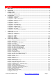
Contents 1. Quick Start ............................................................................................................................................. 6 2. Introduction.......................................................................................................................................... 10 3. Getting Started..................................................................................................................................... 11 Building An RTU ...........
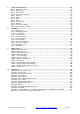
7. Communication Drivers .................................................................................................................... 143 Driver - Kingfisher Series I .................................................................................................................. 143 Driver - Omron PLC ............................................................................................................................. 145 Driver - Allen Bradley..............................................
Section 2 - LP-2/3 Low Power RTU Product Manual 1. Introduction............................................................................................................................................ 4 LP-2/3 Features ....................................................................................................................................... 4 2. Quick Start .....................................................................................................................................
1. Quick Start This chapter explains how to create and download a basic configuration for a PC-1, CP-10/11/21 or LP1/2/3 RTU using Toolbox 32. CP-30 / G30 RTUs are configured using Toolbox PLUS+ and ISaGRAF. This may be a large manual but you only have to read what you need! The steps below will guide you. 1. To Install Toolbox 32 run SETUP.EXE (Toolbox 32 cannot be installed on a server or run over a network). Latest Versions: Toolbox upgrade files are available from www.csesemaphore.
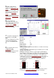
5. Start Toolbox. Ensure Toolbox is using the correct COM port in Configuration - PC Setup. The address and baudrate of the RTU can then be automatically detected using View, Auto Detect. For more information, please see Getting Started, Communicating With An RTU. CP-11/21 OK L1 L2 P1 Tx P2 Tx P3 Tx Rx Rx Rx RTS RTS RTS CD CD CD Vbak The RTU port Rx light will flash each time Toolbox communicates 6.
9. Save the configuration by selecting File, Save. 10. Extra functionality is added to the RTU using firmware drivers. Drivers include Modbus, DNP3, SMS paging, AGA calculations and many more. A driver listing (protocols.pdf) is available from www.cse-semaphore.com/mykingfisher. Standard drivers are available from the website and can be downloaded by selecting Utilities, Advanced, Download Firmware Driver. 11. Download the configuration file (Filename.
13. Ladder logic must be compiled before it is downloaded. First select Ladder (or Logic), Compile and then select Ladder (or Logic), Download To RTU. 14. The RTU is now configured and ready for operation! The RTU can be checked by selecting View, RTU Status. Check that I/O Processing and Logic Processing are both enabled and that the RTU time is updating and correct. The clock can be set from Utilities, Set Real Time Clock. Toolbox 32 User Manual 1.47d www.cse-semaphore.
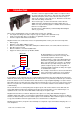
2. Introduction An RTU is electronic equipment that contains a computer. RTUs are often located in remote places. This led to the name Remote Telemetry Unit (RTU). RTUs can be wired to a whole range of devices like switches, relays and sensors. Each RTU can monitor and control the things it is wired to. There are two types of devices that an RTU can be wired to digital and analog. A digital signal is an ON or OFF state of a switch or a relay.
3. Getting Started Building An RTU Every RTU must have a power supply and a processor (CPU) module. Most RTUs also have some inputs and outputs as well. The two main types of power supplies are a PSU-3 and a PS-11/21. The two main types of processors are a PC-1 and a CP-11/21. A PSU-3 is used with a PC-1 and a PS-11/21 is used with a CP11/21 as shown below. A wide variety of input and output modules are available and these can be used in any combination.
Communicating With An RTU Local RTU • Connect the Toolbox cable to port 1 of the RTU as shown below. Note: if there are only USB ports on the PC (and no DB9 serial COM ports), a USB to 9-pin [DB9 male] RS-232 serial converter cable will be required. CP11 PC-1 Port 1 Adaptor ADP-05 RJ45 Cable DB9 PC Serial Port DB9 Male To PC USB Port • COM port 1 and a baud rate of 9600 are commonly used between the PC and RTU.
Remote RTU MASTER RTU1 REMOTE RTU2 REMOTE RTU3 • Once communications with the local RTU have been established (please see above), it is possible to communicate with remote RTUs that are connected to the local RTU. This will only work if the local RTU has been configured with the appropriate network links (please see the topic Configuration, Network List for more information). • Load the RTU configurations for the remote RTUs.
4.
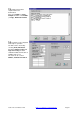
Configuration - New Project A project is used to group all the RTU Configurations in a telemetry system. To create a new project select File, Open new or existing Project... The window below will then be displayed. First double-click on the yellow Folders to select where to store the new project. The project path can have up to 240 characters and may contain spaces. Then enter the file name and select OK. The file name can have up to 130 characters and may contain spaces.
Configuration - New Site After a project has been created or opened, an RTU site can now be created. An RTU site (Filename.SDB) is a text file that contains all the communication settings for the RTU. To create a new site, select File (or Project), Add a Site or Logic File. The window shown below will then be displayed. Enter a file name with no extension eg. Pump Station (as shown above) and then select OK. The file name can have up to 130 characters and may contain spaces.
After selecting OK, the new site will now appear in the project window as shown below. When a Project file is open (ie. it is the active window), RTU sites can be added or removed from the project by using the menu Project, Add A Site Or Logic File or Project, Remove Site. By double-clicking on “Site 001: …” etc in the project window, the Pump Station.SDB file will appear. The RTU settings can then be configured using the Configuration menu.
Configuration - Address & Description Each RTU in the telemetry system should have a unique address. This allows the RTUs to communicate with each other one at a time and avoids communication fails. Figure: Address And Description window (displayed if a project is being used) Site Address: (0-249) Address 250 is reserved for paging parameters and addresses 251 to 255 are reserved for Toolbox (Configuration, PC Setup, PC’s Network Address) as a PC running Toolbox is treated like an RTU.
Configuration - System Parameters Use to configure general RTU settings. Please ensure RTU/CPU Type is set to the type of processor module that is being used. The default values for the other parameters can be used in most cases and are detailed below. Figure: Example System Parameters For A Master RTU Figure: Example System Parameters For An Outstation RTU Toolbox 32 User Manual 1.47d www.cse-semaphore.
RTU Type: The type of processor used by the RTU: CP-1, PC-1, CP-10/11, CP-21, SBX, ERS Micro, LP1/2/3, SB-1, Micro-4 or Other. This setting allows Toolbox to compile ladder logic in the correct format (for each microprocessor type). Note a CP-30 or G30 is configured using Toolbox PLUS+ software. I/O Scan Interval: The period (in milliseconds) at which the RTU scans all its IO modules and processes ladder logic (default = 100 ms).
Global Timeout: This parameter is used with the Timeout setting of the Network List for each network RTU. An RTU will wait for Timeout milliseconds for a reply to its first message attempt. If more attempts are required, the RTU will wait a combination of Timeout and Global Timeout milliseconds before initiating the next attempt or recording a message failure as detailed in the Timeout section of the Network List.
For example, an RTU can be configured to switch its output voltages on after 5 minutes, wait two seconds, scan all the IO modules for 10 seconds and then switch off its output voltages. The time intervals used in this process are configured using the following parameters: • Interval: The period of time (in seconds) that the output voltages are switched off for. To disable Power Saving Control, set Interval to zero.
Configuration - Memory Each RTU has battery backed RAM (SRAM) that is used to store information about that RTU. Some memory is reserved by the RTU for storing module data, local registers, configuration parameters and other information used by the operating system. The remaining memory is configurable and is used to store event logs, ladder logic, network data, phone numbers, images and firmware drivers.
Network Reg. Blocks: Set to 1 or greater to allow the RTU to store data from a remote RTU. 1K per outstation RTU is usually enough. If the network data is overflowed, a Netblocks Overrun error will be triggered (please see #YFLAGS.9) and displayed in the RTU Status. When the RTU is cold-started, all the network blocks are cleared. Calculating the Network Register Blocks Required Analog, digital and local register information is all stored in separate network register blocks.
Check Memory Usage: Provides details about the memory usage of the RTU configuration file. Will also attempt to communicate with the RTU and display the available memory in the RTU. Eg: Toolbox 32 User Manual 1.47d www.cse-semaphore.
Configuration - Port List Defines the settings for each of the 16 possible communication ports of an RTU. The settings for each port can be configured by selecting the Port button (1 to 16). Port: Not configurable. Module: The module type and the port number to configure. A PC-1 has one fixed RS232 port and one option port. A CP10/11/21 or MC-10/11 has one fixed RS232 port and two option ports. An LP-1/2/3 has two fixed serial ports and one (LP-2) or two (LP-1/3) option ports.
Type: The type of the port as labelled on the RTU module. Option boards installed on CP-xx modules are displayed from the Hardware Overview as None (no option board installed), UART Detected (SER-S, SER-I, V34-D, Line-2, Fibre or HART option board), PSTN Modem (V22-d option board) Ethernet (E'NET-E or E'NET option board), Line Modem / Radio (LINE-L option board) or Image (IMAGE-J option board).
• • • GPRS: General Packet Radio Services. Allows connection to an original GPRS modem when using the GPRS firmware driver. Please see the topic Example - GPRS Modems. SS Radio: Spread spectrum radio option board or external radio. Allows an initialisation string to be set to the radio by selecting the Configure button as shown in the topic Configuration - Spread Spectrum Radio. To obtain radio data or for other port settings please see the topic Driver - Spread Spectrum Radio.
Protocol: The protocol that the RTU is able to use on the port. Protocols require a firmware driver* to be loaded in the RTU and cannot be used with other protocols on the same port (with the exception of Modbus and Kingfisher). The available protocols are: • Series 2: Kingfisher Series 2 protocol. This is the default Protocol setting. • ADS Data Logger: Device protocol. • Allen Bradley: Allen Bradley PLC. • ALERT: Radio reporting gauge. • Alstrom Relay: Device protocol. • ASCII No Parity: Device protocol.
• • • • • • • • • • • • • • • • • • • • • • • • • • • with its own network data corresponding to that RTU. The local RTU will also relay Modbus output messages in either Series 1, Series 2 or Modbus format. Modbus messages are relayed in Series 1 format to outstations that have a system ID of AC or in Series 2 format to outstations that have a system ID of AE. Modbus messages are relayed in Modbus format if the port that the RTU relays the message out of is configured as a Modbus initiating port.
# Note 1: When using the Modbus port protocols, some addresses cannot be used for external Modbus devices. These addresses correspond to the SYNC characters used for the Series 2 and Series 1 protocols. Since Modbus messages begin with the Modbus device address, these messages can be confused with Series 2 and Series 1 messages which begin with sync characters AE (Series 2), AC (Series 1 CPU3) or A5 (Series 1 CPU1).
Configuration - PSTN If the port type is set to PSTN, selecting the Configure button will display the following window. Note: the first 4 parameters also apply to GPRS modems. Figure: Default PSTN Configuration Window showing Initialisation String for an External Modem or GSM. Dial Retries: The number of times that the RTU will attempt to re-dial the target RTU. The time waited before performing the next dialing attempt changes according to the dialing attempt number.
Remaining Online To remain online after connection, set On Line Inactivity to 0 and Hang Up After to 0 in both RTUs in the PSTN link. If the line is disconnected, the RTU will reconnect when the next TX or RX message is initiated from ladder logic. Init String: (0-29 characters) These characters are sent to the modem to initialise it after startup, after disconnection and if a dial attempt fails.
Configuration - TMR If the port type is set to TMR (Trunk Mobile Radio), selecting the Configure button will display the following options: On Line Inactivity: (0-32767) The RTU will hang up after this amount of time has elapsed since the last message received. A value of 0 disables the function. Hang Up After: (0-32767) The RTU will hang up after this amount of time has elapsed after connection or after sending the last message. A value of 0 disables this function.
Configuration – RADIO / PLINE If the port type is set to RADIO or PLINE, selecting the Configure button will display the following options. Note: attenuation Level only applies to the superseded LINE-L option boards. Attenuation Level: (0-15) The TX Audio output level is reduced in power by this amount. The default setting 0 maintains the maximum output power (-6 dBm).
Configuration - LP-1 Integrated Radio Superseded LP-1 hardware option. If the port type is set to LP-1 FFSK P3, selecting the Configure button will display the following options: Rx Frequency: (0-512,000,000 Hz) The frequency of incoming messages. Tx Frequency: (0-512,000,000 Hz) The frequency of outgoing messages. Min Rx Detection Level: (90-120 dB) The weakest detectable signal strength. Note: radio noise is received between -120 to -108 dB. A setting of 90 (ie. -90dB) is recommended.
Configuration - Ethernet If the port type is set to Ethernet, selecting the Configure button will display the following options: IP Address: A local area network may be used to communicate with an RTU that has an Ethernet option board. Each number in the IP address can have values in the range of 0-255. The IP address can then be used by Toolbox to communicate with the RTU via Ethernet.
Configuration - Spread Spectrum Radio If the port type is set to SS_RADIO, selecting the Configure button will display the following options: The spread spectrum radio uses extended AT commands to set or read various parameters. Default String: The beginning of the initialisation string sent to the radio.
Advanced Radio Configuration A spread spectrum radio can be initialised using the Toolbox Comms Terminal. Eg. for RTU1 with an SS radio option board on port 2, the following Comms Terminal settings would be used: Once Comms Terminal has started, the radio may first need to be put into command mode by sending +++ . Commands can then be sent to the radio.
Configuration - Network List The Network List tells the local RTU how to communicate with remote RTUs. By default, an RTU will automatically create or update links in its network list if a message is received that is new or is different to an existing link. Eg. if an RTU has a network link to RTU2 using port 2 and a message is received from RTU2 on port 3, the network link will be updated to port 3. This feature can be disabled using ladder logic (by setting #YMODE.
A blank network list is shown below. A network link can be added by selecting the button at the start of a blank row. After selecting a button, a window will appear as shown below. Target RTU: (0-249) The address of the RTU to communicate with. Toolbox 32 User Manual 1.47d www.cse-semaphore.
System ID: This is the communications sync character used at the start of outgoing Kingfisher messages. An RTU will only respond to Kingfisher messages that begin with the same System ID as the RTU's own system ID (as configured in Configuration, System Parameters) or that begin with AE (Hexadecimal). System ID is not used by other protocols. Default system IDs for Kingfisher messages are as follows: • AE - Default for Series 2 RTUs.
Timeout: The time that an RTU will wait for a reply to its first message. If Message Retries is set to 1 or greater, the RTU will try sending the message again. The time waited for a reply to all other message attempts depends on how many message attempts have already been sent and on the Global Timeout setting (as defined in Configuration, System Parameters) as detailed below.
Configuration - I/O Modules List The I/O Modules list is a list of all the modules to be used in the RTU. If the I/O Modules List is configured, Toolbox will check that it matches the modules in the local RTU before downloading the configuration. A warning message will appear if there are any differences. The I/O modules list also allows the various module options to be configured eg. AI-4 scanning rate, DO-2 failsafe outputs or AI-10 input range.
Configuration - I/O Modules List Options Scan Priority: (All IO modules) Three priorities are available - High (read IO every scan interval), Medium (read IO once every 3 scan intervals) and Low (read IO once every 10 scan intervals). By default, the scan priority is set to High. For some large RTUs, rapidly scanning all the analog inputs slows down the RTU and is unnecessary. To speed up large RTUs, the analog input modules can be configured to have a Low Scan Priority.
Configuration - DI-10 The DI-10 Module is a 16 channel Digital Input module with configurable Frequency or Pulse or Quadrature counting and Sequence-of-Events recording. After the DI-10 module has been added to the IO modules list, these options can be configured. Note: Sequence of Events is not supported when the DI-10 is used with a PC-1 or CP-1 processor module. Slot Address: (1 to 64) The slot address of the DI-10.
Debounce Filters: (None, 1ms, 3ms, 10ms, 30ms, 100ms, 250ms and AC Filter) These software debounce filters are grouped into configurable filters for channels 1-4, 5-8, 9-12, and 13-16. If a software debounce filter is selected, the logical input in the digital input register will not change to a new state until the actual input has been at the new state continuously for the specified filter time. Note: the sample time for the software debounce filters is in excess of 10 kHz (< 0.1ms between samples).
Configuration - Phone Directory The phone directory is used to specify up to 256 phone numbers that an RTU can dial (or up to 512 phone numbers including the secondary phone numbers). By selecting one of the row buttons the window shown below is displayed. Target RTU: (0-249) The remote RTU that is to be dialed. When using leased line modems (PSTN modems that are hardwired), the Target RTU must be defined even though a phone number is not dialed.
Configuration - Pager Configuration When paging is configured, RTU250 is automatically added to the Network List and is used for the paging communication fail and success counters. The RTU will send each pager message up to 3 times. Each time the pager message is transmitted, it can be sent to the same group of pager receivers or to a different group of pager receivers. The pager message will not be sent to the next group of pager receivers if the RTU receives an acknowledge within the configured time.
Pager Type: The type of paging service to be used. The following options are available: • None: Paging is not configured. Selecting None prevents the paging parameters from being downloaded into the RTU and avoids Toolbox checking if the RTU contains the paging driver. • PET protocol (TAP): Standard paging protocol. • Airtouch: USA Paging service. • Pagenet: USA Paging service. • Radio Pager: Imark pager transmitter radio.
Relaying Pager Messages When a pager message is to be relayed, the initiating RTU will send the text (plus time and date) and the pager number indexes to the pager RTU. This means the RTU that initiates the pager message uses its own pager sequences but not its own pager numbers. The pager numbers configured in the pager RTU (the RTU that dials the paging service or has the pager radio) are used to target the pager receivers.
Configuration - PC Setup Contains the Toolbox communication settings. The default settings are shown below. Usually these settings do not need to be changed except when communicating with a remote RTU over a network. When communicating over a network, it may be necessary to set Comms Timeout to 5 or more seconds and set the number of retries to 1 or more (especially when downloading an RTU configuration over the network). PC Port: (COM 1- 48 or Ethernet) The PC's communication port to use.
Comms Repeat Rate (sec): (Continuous, 0.1, 0.2, 0.5, 1, 2, 5, 10, 30, 60) The rate at which Toolbox generates a new message request. For example, when viewing the local registers with a Comms Repeat Rate of 0.5 seconds, a read request for local registers will be sent every 0.5 seconds. If a message fails, Toolbox will wait until the failed message has timed out (after Comms Timeout seconds) and then will send the next message at the next 0.5 second time interval.
Configuration - Download RTU Configuration First ensure that Toolbox can communicate with the target RTU. Please see the topic Getting Started Communicating With An RTU for more information. Before downloading a completely new configuration to the local RTU it is recommended that the RTU is first Cold Started (Utilities, Advanced, Cold Start.) Caution! Cold starting a remote RTU is not recommended.
5. Ladder Logic Overview What ladder logic is and how it works Parameters Registers used by ladder logic blocks Variables List Optional: create a variables list for ladder logic. Allows data labels to be used instead of register addresses. Editing Editing tips. Includes how to check which registers have already been used.
Ladder Logic - Overview Ladder Logic is used to add intelligence to the RTU. It can be programmed to monitor inputs, control outputs and communicate with other RTUs or devices. Input Blocks • • • • • • • • • • • Output Blocks Ladder Logic is a series of logic blocks arranged in the shape of a physical ladder Blocks are processed from left to right and from top to bottom Ladder logic blocks are configured on pages. Each page can have up to 7 lines (or rungs) of ladder logic.
Ladder Logic - Parameters A Kingfisher RTU stores all I/O points, configuration settings and data variables in 16-bit registers. Ladder logic is able to read and write to most of these registers allowing the RTU to perform a wide range of functions - including the ability to reconfigure itself. In addition to these registers, constants and indirect addressing may also be used for ladder logic parameters (where applicable) as detailed below. RTU Register Types #AIss.c #AOss.c #DIss.cc #DOss.
Indirect Addressing When addressing a register, the register number is usually hardcoded in the address eg. #R1. The register number can also be specified indirectly by putting the register number in another register (the pointer register) and then using indirect addressing. If the pointer register contains a value that will point out of range (eg. 0 or 3000), the indirect register address will return an incorrect value.
Ladder Logic - Variables List Optional. Allows inputs, outputs and parameters to be defined in a list. The list can then be accessed when configuring ladder logic. The Variables List reduces configuration errors and maintains consistency in labelling ladder logic blocks. The variables list can be used to create a database of RTU data to read and write for SCADA software. For more than one RTU site, the variables from all the RTU sites in the project can be accessed from the variable selection list.
Variables List Format The variables list is saved as a text file Filename.VAR for each RTU site. A single VAR file can be used for all the RTUs in a telemetry system by creating copies of the master VAR file and renaming them to match each RTU site. The VAR file can be edited using Microsoft Notepad or Excel. Note: if using Excel, ensure the file is saved as a Text (Tab delimited) file. The file will then need to be renamed from Filename.VAR.txt back to Filename.VAR.
Replicating Variables After selecting a variable in the variables list and then selecting the Replicate button, a replication template will appear that initially uses the settings of the selected variable. The replication template for Counter1 is shown. Characters in the template are replaced with wildcards or left as they are to be copied into the new variables as shown. The variables created when OK is selected are shown. Toolbox 32 User Manual 1.47d www.cse-semaphore.
The following wildcards can be used to replace characters in the replication template: (xT+y,a,b) or (xT-y,a,b) or # or * x T + or y ,a,b # * (Optional) Number of characters in the starting template to modify Type of conversion: c = character conversion, n = number conversion. Character conversions apply to characters in the range (A-Z, a-z, 0-9) and number conversions apply to integer numbers. A 9 will be incremented to 0 in a character conversion, but to 10 in a number conversion.
Ladder Logic - Editing A ladder block can be edited by double-clicking on it or by pressing Enter when the block is highlighted. Double-clicking or pressing Enter on an empty ladder position will display a list of new blocks that can be added. Ladder logic can be copied, cut and pasted using the same standard key commands as a word processor as detailed below. Ladder logic can also be copied from one ladder to another if two or more sites are open in Toolbox.
Ladder Logic - Inputs Each type of ladder input block has a 12-character comment field that is used to describe the active state of the block (ie. when it is logically TRUE). For a single parameter block, the comment is used as a tagname (a data descriptor) to describe the active state of that parameter eg. Pump1Running. For multiple parameter blocks, the comment can be used to describe the purpose of the block eg. Lev>HiSetpt? Input blocks include: Contact, Compare, Logical Mask, Edge Trigger and Timer.
Ladder Logic - Compare All comparisons use unsigned values. This means that negative numbers are treated as large positive numbers. Compare: Less Than Block is true when parameter 1 is less than parameter 2. Eg. if #R1 is less than #R2. As used in the topic Example - Exception Reporting Analogs. Compare: Less Or Equal Block is true when parameter 1 is less than or equal to parameter 2. Eg. if R1 is less than or equal to R2. Compare: Equal To Block is true when parameter 1 is equal to parameter 2. Eg.
Ladder Logic - Logical Mask Logical masking allows individual register bits to be selected and used for a Boolean operation. Each Logical Mask block is configured using two parameters as follows: Test Register: Any 16-bit register. Bit Mask: (Constant or #R) The Bit Mask parameter is normally entered as a hexadecimal number in the format 16#xxxx - where xxxx is the hexadecimal number. For a description of hexadecimal numbers please see the appendix - Hexadecimal Numbers.
Ladder Logic - Edge Trigger Caution! After downloading ladder logic, a Positive Edge Trigger or Change block will be TRUE for one ladder scan if the test bit is TRUE. This can be prevented by also testing the system register flag #YSYS.ENABLE. Note: a warm start or a power reset will not affect these blocks. Positive Edge Trigger Block is true for one ladder scan when the test bit makes an OFF to ON transition (0 to 1). Eg. bit 1 of R1 makes a 0 to 1 transition.
Ladder Logic - Timer The following parameters are used by each Timer block: Timer Register: (#T1 to #T64) Each timer register can only be used once in ladder logic. Note: for standard time intervals (eg. 1 second, 1 minute, 1 hour), it is recommended that Timer Flags (eg. #YTICK.SEC ) be used instead of a Periodic Timer block. Unlike Timer registers, Timer Flags can be used multiple times in ladder logic. Period: (Constant or #R).
Ladder Logic - Outputs The right-most column of ladder logic is used for Ladder Output blocks. These blocks cause something to happen - like a register bit to be set, a message to be transmitted or a calculation to be performed. Ladder Output blocks are processed when connected to a ladder rung that is logically true. The various types of ladder outputs are detailed in the following sections.
Ladder Logic - Copy Single Copy Copies a Source bit or register (eg. #R2) to a Destination bit or register (eg. #R1). Source: Constant, bit, 16-bit register, float or long. Any addressable bit (eg. #R1.5, #DI14.1, #YLST2.1, #NR2.1.5, #ND2.14.1) or register (eg. #R1, #F1, #DI14, #YLSUCC2, #YSEC) can be used. For more Source options, please see the appendix - RTU Data. Destination: Bit, 16-bit register, float or long.
String Copy Copies up to 31 text characters (a string) to consecutive local registers. Each character is stored as an 8-bit ASCII number and the string is null terminated. Two characters are stored in each local register. For each pair of characters, the left character is stored in channels 1-8 and the right character is stored in channels 916. For an LP-1/2/3, the characters are stored in reverse order. Eg.
Ladder Logic - Maths 16-bit Register Range 0-65535 (unsigned) or -32768 to +32767 (signed). Values overflowing the storage limit are counted from zero again. Eg. 65535 + 1 is stored as 0, 65535 + 2 is stored as 1. Values less than zero are counted backwards from 0. Eg. -1 is stored as 65535, -2 is stored as 65534. All Kingfisher addresses (ie.
Subtract Parameter 2 (R3) is subtracted from Parameter 1 (R2) and the result is put in the Destination (R1). As used in the topic Example - Flow Totalisation. Destination: 16-bit register (read/write), Long or Float register. Parameter 1, Parameter 2: 16-bit register (read/write), Long or Float register or constant. Register types can be mixed in any order. Caution! It is possible to exceed the range of the destination register and produce an undefined result.
Modulus Calculates the modulus of Parameter 1 divided by Parameter 2 and returns the result in the Destination. The modulus is the remainder after division and is represented by the percentage symbol (%). Eg. 10 % 3 = 1 (10 divided by 3 equals 3, with a remainder of 1). The Modulus block treats 16-bit registers as signed numbers (32767 to +32767, highest bit = sign). Destination: 16-bit register (read/write, signed) or Long register (not Float).
Exponential Calculates Parameter 1 (F3) to the power of Parameter 2 (F5) and returns the result in the Destination (F1). Destination: Float register. Parameter 1, 2: Float register or constant. Logarithm Calculates the Logarithm (base 10) of the Source (F3) and stores the result in the Destination (F1). Destination: Float register. Source: Float register or constant. Sine Calculates the Sine of the Source (F3) and stores the result in the Destination (F1). Angles are defined in o radians.
BCD To Binary Converts a BCD number (#R1) to binary format (#R2). BCD uses a group of 4 bits to represent each decimal digit (0-9). Not supported by CP-21. Destination: 16-bit register (read/write). Source: 16-bit register (read/write) or constant. Binary To BCD Converts a binary number (#R1) to BCD format (#R2). BCD uses a group of 4 bits to represent each decimal digit (0-9). Not supported by CP-21. Destination: 16-bit register (read/write). Source: 16-bit register (read/write) or constant.
Ladder Logic - Logic For each of the following Logic Functions, the input parameters can be 16-bit registers or constants. These functions all perform bit-wise operations; ie. they treat the registers as 16 individual bits. Invert The Source (R2) is inverted, and placed in the Destination (R1). An Invert causes all the 16-bits in the register to be changed (ie. 1's are changed to 0's and 0's are changed to 1's).
ROL (Rotate Left) Parameter 1 is rotated left by the number of bits specified in Parameter 2, and the result placed in the Destination. Eg. Destination = #R1, Parameter 1 = #R1, Parameter 2 = 1 If #R1 initially contains the value 10 hex (0000 0000 0001 0000 binary), it will contain 20 hex (0000 0000 0010 0000 binary) after calling this function. If #R1 initially contains the value 8000 hex (1000 0000 0000 0000 binary), it will contain 1 hex (0000 0000 0000 0001 binary) after calling this function.
Ladder Logic - Event Logging Event logs allow the RTU to record time and date stamped data. An event log can be created periodically, after data changes or on any configurable event. Event logs are kept in a circular buffer that is "max. number of logs" long (as detailed by the Memory configuration, Check memory usage button). When the buffer is full, the oldest logs are overwritten. The RTU uses an internal "current pointer" which always points to the latest log added to the buffer.
Tx Event Logs No longer supported. Please use Tx Update Event Logs block. Tx Update Event Logs This block is designed to update event logs in a standby master RTU. It also updates the event log pointers for the remote RTUs in the standby master. The block checks if new logs need to be transmitted to the destination RTU and then sends them 10 at a time until it has sent the maximum limit of event logs or until the end of the event log list is reached. Requires driver TXUPDATE.Dxx.
Rx Event Logs No longer supported. Please use the Rx Update RTU Info block. Rx Event Logs from Specific Period Polls event logs that occurred over a specific time period from a remote RTU. It will keep polling groups of 10 logs at a time until it has received the maximum limit of logs or until the end of the event log list is reached. RTU: (1-249) The target RTU to poll the event logs from.
Get Event Log Count No longer supported. Set Event Log Pointer No longer supported. Pack Event Logs Compacts the local Event Log list by deleting event logs that are older than the specified period. Not supported by CP-21. Log Retention Period: These fields indicate time in hours before now. They specify the period for which logs of each priority will be retained. All event logs older than the specified period will be deleted.
Ladder Logic - Tx / Rx Comms The following Kingfisher blocks are detailed below: Tx/Rx Data, Tx/Rx Images and Rx Update. Please see the Communication Drivers chapter for more protocol drivers. Ladder Logic - Transmit / Receive Data Whenever data is transferred from one RTU to another, the data is always placed in network registers. When communicating with an RTU connected with a PSTN modem link, the RTU will automatically dial the number configured for that RTU.
Ladder Logic - Tx/Rx Update Network RTU Images Care must be taken to initiate only one Tx or Rx Update block at a time otherwise unpredictable results may occur. The pending flags detailed below can be used to determine when the block has finished before generating new Tx or Rx update messages. Series 2: Tx Update Network RTU Images Sends new network data to a destination RTU. It is possible to update the network data for up to 32 RTUs using one TX Images block.
Ladder Logic - Rx Update RTU Info Series 2: Rx Update RTU Info Polls data and event logs from up to 16 RTUs. An RX Update block can also issue a Sync Clock command to each of the RTUs. The Rx Update block works by requesting the CRC for each network block from each RTU and then requests the blocks that have changed. Only network blocks that are different are updated which minimises communication time.
Series 2: Rx Update RTU Info, single RTU Polls data and event logs from a single RTU. An RX Update block can also issue a Sync Clock command to the RTU. The Rx Update block works by requesting the CRC for each block and then requesting the blocks which have changed. Only network blocks that are different are updated which minimises communication time. Event logs that match the priority and user type are uploaded until the maximum limit is reached or until there are no more event logs.
Ladder Logic - Pager Message Pager Message Sends a 32-character pager message to up to 12 pager receivers. The pager message can also be sent with a time and date stamp. Requires driver PAGINGxx.Dxx. A pager message will initially be sent to the pager receiver(s) configured in Group 1 of the selected pager sequence. If an acknowledge is received within the time specified in the Wait for Ack field (by writing a 0 to the acknowledge bit), the sequence is completed and no further action is taken.
Ladder Logic - Function And Program Blocks Function Blocks allow commonly used pieces of logic to be defined once and then re-used as many times as necessary. Up to 32 variables can be passed to a function block and then used within the function block. Variables are referenced by "%number"; eg. the third parameter would be referenced as "%3". A function block definition commences with a Start Function Block, and ends with a Return from Function Block.
Call Calls a function defined in the ladder. As used in the topic Example – Time Based Rolling Averages. Call Function: The name of the function block to call. This name must be entered exactly as it appears in the corresponding Start Function block (it is case sensitive). To be used as an input, the function block called must have a return variable of Boolean. To be used as an output, the function block called must have a return variable of None.
End Stops processing of the ladder at that point. This can improve the scan rate of ladder logic by preventing the unnecessary scanning of ladder logic located after the End block. An End block is automatically inserted into the compiled output file just before the definition of the first function block. Caution! An End block must NEVER be used within a function block as it will prevent the function block from correctly finishing and may cause the RTU to behave unpredictably. Toolbox 32 User Manual 1.
Ladder Logic - P.I.D. Block The PID block is used to monitor a process variable (eg. flowrate) and compare it to a setpoint (eg. desired flowrate). According to the difference between the actual value and the setpoint value, the PID block sets a Control Variable (eg. valve position) to reduce the error. The control variable is gradually changed until the desired setpoint is achieved within the deadband limits.
Set Point: (16-bit register or constant [0 to 32767]) This is the desired process result. The PID output will be continually adjusted until the Process Variable reaches this setpoint. The setpoint is given the same units or scaling as the Process Variable and so if an analog input is being monitored the setpoint should have a range of 0-32760 (0.00 - 100.00%).
Direct Proportional Response PV SP CV Direct Integral Response SP PV CV Direct Derivative Response SP PV CV Auto (0) / Man (1): (Bit) When in manual mode, the PID block uses the Raise and Lower parameters to control the output. When in auto mode, the PID block adjusts the Control Variable until it is within the Deadband settings of the Set Point. Raise (1 = Raise O/P): (1=enabled, 0=disabled) Only used in manual mode.
Ladder Logic - AGA-8 AGA-8 Gas Compressibility (Gross calculation) Uses the American Gas Association standard AGA-8 for calculating gas compressibility. Requires driver AGA8.Dxx. Comment: A 12-character description. Temperature (deg C): (Float) Gas temperature. Pressure (MPa): (Float) Gas pressure. Mole Fraction N2: (Float) Mole fraction of Nitrogen in the gas mixture. Mole Fraction CO2: (Float) Mole fraction of Carbon Dioxide in the gas mixture.
Example: o Temperature 0C Pressure 0.6894757 Mpa Mole N2 0.002595 Mole CO2 0.005956 Specific Gravity 0.581078 o Reference Temperature 15.56 C Reference Pressure 0.101560 Mpa Result: Compressibility=0.982387, Status=0. AGA-7 Gas Flow This formula uses the compressibility output from the AGA-8 block and can be written in ladder to evaluate the AGA-7 gas flow (note: an example configuration is available from www.csesemaphore.com/mykingfisher).
AGA-8 Gas Compressibility (Detailed calculation) Uses the American Gas Association standard AGA-8 for calculating gas compressibility using the detailed characterization method. Requires driver AGA8DET.Dxx. The driver is based entirely on Compressibility Factors of Natural Gas and Other Related Hydrocarbon Gases, AGA Transmission Measurement Committee Report No. 8, Second Edition, November 1992. Comment: A 12-character description. Compressibility: (Float) AGA-8 compressibility factor of the gas.
Ladder Logic - AGA-9 Steam Flow Calc Calculates steam flow using the AGA-9 standard and the published tables of superheated steam density. Requires driver AGA9.Dxx.
• • • Ch1: Calculation error (indicates steam is saturated) Ch2: Pressure out-of-range error (allowed range is 0 to 7000 MPa) o Ch3: Temperature out-of-range error (allowed range is 100 to 700 C) Examples: o Temperature 190 C Pressure 2000 kPa Differential Pres. 20 kPa K 0.05 Result: Volumetric Steam Flow=0, Steam Density=0, Status=1 (saturated) o Temperature 200 C Pressure 1000 kPa Differential Pres. 100 kPa K 0.1 Result: Volumetric Steam Flow=2.20318, Steam Density=4.
Ladder Logic - Clock Synchronization Synchronizes the RTU's real-time clock. There are two modes of operation: • Single RTU Sync: Forces the real-time clock of the target RTU to match the local RTU. • Global RTU Sync: Sends a global command to synchronize all RTUs that are connected to the same comms port as the target RTU. In both modes of operation, the communication delay is first measured between the local RTU and the target RTU.
Ladder Logic - Report Printer Prints a text file to a serial printer. The text file may contain RTU variables. The text file is compiled with the ladder logic and stored in the RTU. Requires driver REPORT.Dxx. Comment: A 12-character description. Filename: The filename is automatically generated and a text file is created with that name. The file can then be edited and various variables and text added as detailed below. When the ladder logic is compiled, the text file is included with the compiled code.
Each variable is defined using the following layout: Address Format Additional strings Where: Address: Any variable as used in ladder logic (eg. #R1, #YDIAG.1). Format: A string defining the display format of the variable. The format string has the following structure: (Note: [ ] denotes an optional parameter) % [Flags] [Width] [.Prec] [_dp] [l] Type Format parameter Flags Width .
Ladder Logic - Image Monitoring Functions Configure Image Parameters Configures an image channel before it is used for the first time or when changing to a new channel. PC1/CP-1 requires driver IMAGExx.DRV to support an MC-xx with an Image Capture option board. Please see the topic Example - Kingfisher Images. Slot Address: (0-64) The slot address of the module with the image option board. Set to 0 for a CP-10/11 or set to the slot address for an MC-10/11.
Get Image Buffer Statistics Monitors the RTU's image memory buffer. PC-1/CP-1 requires driver IMAGExx.DRV to support an MC-xx with an Image Capture option board. Slot Address: (0-64) The slot address of the module with the image option board. Set to 0 for a CP-10/11 or set to the slot address for an MC-10/11. Total Images: (Optional local register) The total number of images that are stored in the RTU. Once the RTU's image buffer is full, this number will not change.
6. Ladder Logic Examples To create or edit ladder logic, select Logic, Edit.
Example - Initialising Variables On First Scan Variables can be initialised after ladder logic is downloaded by using the logic below. To initialise variables after a warm start or power reset or after downloading the SDB file, use #YSYS.SCAN1 instead of #YSYS.ENABLE. │ │ ├Initialise registers after downloading ladder logic ┼ ┤ │ │ │LadderDownld R1QuietTimer │ │#YSYS.
Example - Counting Pulses And Starts Counting Pulses Using A Standard Digital Input (DI-1, IO-x) An RTU is capable of counting input pulses up to a rate of at least 10 Hz. The actual pulse rate that the RTU can count depends on how often it is able to scan its ladder. Since pulses are counted by counting the rising or falling edges of digital inputs, the ladder needs to be scanned fast enough to allow the RTU to register the pulse in the ACTIVE and in the INACTIVE states.
Counting Pulses Using A DI-5 A DI-5 Counter Module automatically keeps pulse totals for its first four digital input channels. For fast pulse rates (up to 10kHz), the pulse totals will reach the maximum value of 65535 very quickly. To prevent a pulse total from overflowing, it can be rolled over every 1000 pulses as shown below. In the example, #AI14.2 is the number of digital input 1 pulses (0-999) and #R14 is the number of thousands of pulses (0-65535 k) for a DI-5 module in slot 14.
Example - Flow Totalisation The following example shows how to accumulate a flow volume from a flowrate analog input. For this example, the flowrate engineering units are 4-20mA=0-100 L/s. Each second, the number of litres that have flowed (FlowLastSec, #R10) is calculated by dividing the analog input by 32760 (the raw analog input range) and then multiplying by 100 (the high limit of the engineering units). This number of litres is then added to the FlowTdy(L) total (#R11).
Example - Exception Reporting Analogs Analog values can be exception reported to the master RTU when there has been a percentage change (of the analog range) from the last reported value. This is done by using two registers, a constant and an analog input. The constant is used to specify the amount the analog value must change by before an exception report is generated. The registers are used to store the last reported value plus the constant and the last reported value minus the constant.
Example - Exception Reporting Digitals An exception report can be generated when a single digital bit changes state or when any of the 16 channels in a hardware or local register change state. The example below shows how to exception report a PC-1 mains power fail. The 30 second on-delay is used to prevent false exception reports caused by the discharge LED flickering ON and OFF (which can happen when the battery is fully charged or is not connected).
Example - Sending The Exception Report An RTU usually has a number of inputs and conditions that can trigger an exception report. Rather than exception report every change separately, it is better if all these conditions set a common flag that causes a single exception report to be sent containing all the RTU data. As shown in the previous sections for exception reporting analogs and digitals, the Update RTU1 flag was set when an exception report was required.
Example - Polling Data Polling is usually performed by the master RTU in order to get a regular update of remote RTU data and to determine if communications to the remote RTUs have failed. The Series 2 protocol allows for full-duplex communications which means that the RTU can simultaneously transmit and receive. However, since most radios are half-duplex, which means that the RTU cannot transmit and receive simultaneously, it is necessary to force the RTU to wait for a reply to each transmit message.
Basic Polling Using Ethernet It is possible to communicate with multiple RTUs at the same time using one Ethernet port. Therefore, instead of checking if the port is busy (waiting for a reply from any RTU), it is better to check if the target RTU is busy as shown below. │ │ ├Poll remote RTUs every 15 minutes ┼ ┼ ┤ │ │ │DoEvery15min Poll Flag 2 │ │ #T1 #R1.2 │ ├──[PERIOD]──────────────────────────────────────────────────────┬─────(S)─────┤ │ 15 Minutes │ │ │ │Poll Flag 3 │ │ │ #R1.
Polling After Data Has Expired If an outstation RTU has exception reported to the master RTU recently, it is not necessary to poll the outstation RTU until the data is older than X minutes (where X is ideally a SCADA setpoint with a default value of say 30 minutes). If exception reports are generated frequently, it may never be necessary to poll the outstation RTU. Communication statistics are still accumulated as a success is recorded for each exception report received.
Example - Event Logging Event Log Pointers Event logs are kept in a circular buffer that is Max number of logs long (as defined in the topic Configuration Memory). When the buffer is full, the oldest logs are overwritten. The RTU uses an internal current pointer to point to the latest log added to the buffer. If an outstation RTU sends its event logs to more than one master RTU, the outstation should use a different pointer for each master RTU.
Example - Polling Event Logs An Rx Update block can be used to poll event logs and data from up to 16 RTUs. The system parameters Update Register Blocks and Update Hardware Blocks are configured in the outstation RTU to control which of the data blocks will be checked or read from the RTU (please see the topic Configuration - System Parameters for more information).
Example - Comms Fails Today And Yesterday Communication fails give a good indication of the state and reliability of the RTU communications network. Communication statistics are automatically recorded by the RTU in Network Link Registers. These network link registers can be accessed by SCADA software by copying them to local registers. At midnight, the fails today values can be copied to fails yesterday registers and then the network link registers reset to zero.
Example - Modems (PSTN, GSM and 3G) PSTN, GSM and 3G (Maxon Modmax MM-6280IND) modems can be used on any serial port of the RTU by configuring the following items: • Configuration, Port List: Set the port Type to PSTN and then select the Configure button. Set the Init String for the type of modem being used. If the PSTN modem or GSM is to be used for dialling a paging service, the default initialisation string may need to be changed as detailed in the topic Configuration Port List, PSTN, Init String.
Example - Radios Various types of external radios require various types of RTU ports and cables. The external radios that are commonly used by Semaphore and the RTU setup for each radio is detailed below. Note: the spread spectrum radio option board is detailed in the topic Driver - Spread Spectrum Radio.
Example - Satellite Phones A satellite phone is treated like a PSTN modem by the RTU and can be used on any serial port. The following setup is for a Motorola 9522 satellite phone. • First ensure that the latest firmware supporting Satellite Phones is loaded in the RTU (as detailed in protocols.pdf available from www.cse-semaphore.com/mykingfisher). • When a satellite phone is first obtained, it usually requires a PIN number to boot up (if this has not already been disabled).
Example - GPRS Modems GPRS (General Packet Radio Services) modems maintain a continuous connection to the GSM mobile network and provide faster data transmission rates than GSM modems. However, data transmissions are not continuous. Data is broken into packets, allowing multiple GPRS modems to share the same channel. This can cause some data transfers to take up to 10 seconds. The following setup is for a Wavecom Fastrack GPRS modem (with TCP/IP stacking enabled) connected to an RTU serial port.
Example - RS485 RS485 can be used on any CP-xx isolated serial port or PC-1 serial port 2. • Configuration, Port List: Set Type to RS485 and set Baudrate to match the remote device (eg. 9600). Set Pre Tx and Post Tx to 10 ms as illustrated below (note: Post Tx can be set to 1ms for fast response RS485 devices). • Configuration, Network List: Set Target RTU to the address of the RTU to communicate with and Port # to the port number configured above.
Example - Private Line Two or four-wire Private Line communications can be used on any CP-xx LINE-L or LINE-2 port. Two-wire private line communications can also be used on PC-1/MC-1 Line option ports. • Configuration, Port List: Set Type to LINE-2 (for LINE-2 ports) or PLINE (for LINE-L or PC-1/MC-1 Line option ports). Set Baud Rate to 1200, Pre TX to 100 (ms) and Post TX to 50 (ms). Note: Pre and Post TX can be reduced to 50 and 10 ms respectively in some installations.
Example - SMS Pager Messages The following example uses a PSTN modem to dial Telstra SMS paging in Australia and send an SMS message to one mobile phone. The RTU has a PSTN modem on port 2 of the CPU. The phone numbers of the mobile phones are 0414 123456, 0415 123456 and 0416 123456. The phone number of the Telstra PET SMS paging service is 125 107. Note that 125 107 only provides service to Telstra lines (if your account is with Optus etc. it won't work).
Since the pager message is only transmitted once, the Acknowledge Bit (#R100.16) is not used. If the pager message was to be transmitted more than once (by configuring a 1 in the 2nd Group and 3rd Group of the 1st Sequence), writing a 0 to #R100.16 would acknowledge the pager message and stop the pager message from being re-transmitted.
If say #Rxx is used for all three groups in the first sequence configured in Configuration, Pager Configuration, then SCADA software can be used to set and reset the individual bits of #Rxx corresponding to the pager receivers to enable or disable. These bits could also be cleared during certain times to prevent pager messages at inconvenient times. Toolbox 32 User Manual 1.47d www.cse-semaphore.
Example - Pager Messages With Variables The previous example showed how a fixed pager message could be sent to a mobile phone as an SMS. Pager messages can also be sent that contain register values. This is achieved by sending a string of up to 31 ASCII characters. The string is overwritten with register values prior to sending the pager message. The string is stored in local registers with two characters in each register (8 bits are used for each character).
│ │ ├Convert Tank Level (0-999=0-99.9%) to ASCII for pager msg ┤ ├Determine number of 100's, 10's and 1's as single integers ┤ │ No of 100s │ │ #YTICK.
Figure: String Copy block used to make the basic pager message string Figure: Pager message block used to transmit a string containing a variable. Toolbox 32 User Manual 1.47d www.cse-semaphore.
Example - Kingfisher Images To configure an RTU to capture images: • First ensure that the latest firmware is loaded in the CPU or MC module (as detailed in protocols.pdf available from www.cse-semaphore.com/mykingfisher). The CPU firmware version can be checked by viewing the RTU Status and the MC firmware version can be checked by viewing the Hardware Overview and selecting the MC module. • If a PC-1/CP-1 is being used with an MC-xx, then the image capture driver (IMAGExx.
│ │ ├Configure image parameters after a warm start ┼ ┤ │ │ │OnFirstScan SetupImageCh3│ │#YSYS.SCAN1 Module 0 │ ├─────┤ ├─────────────────────────────────────────────────────────(ConfigImage)┤ │ │ ├Determine when RTU is ready to capture the next image ┤ │ #R6=NextImgNo│ │ Module 0 │ ├─────────────────────────────────────────────────────────────────(ImageStats)─┤ │ │ │NextImageNo. CameraReady │ │ #R6 #R1.
Using Multiple Cameras Each CP-10/11 or MC-10/11 module is treated as a 4 channel image capture module. One memory buffer is allocated for all the images from the 4 channels. Each MC-10/11 also has its own image buffer (256 KB). Before capturing an image, the image channel must first be configured (using the Configure Image Capture Parameters ladder block). It takes about 0.5 seconds for the image option board to be armed and ready to capture an image.
Example - Low Power Mode The RTU has two low power modes - IO power saving and power down. IO power saving mode is configured from Configuration, System Parameters, I/O Power Saving Control. In IO power saving mode, the RTU can be configured to switch off various output voltages (eg. 24VDC from the BA-4 and from IO modules such as the AI-10, IO-4 etc) but in this mode the processor (eg. PC-1) keeps running. Power down mode switches off the various RTU output voltages and also puts the processor to sleep.
Example - RTU Diagnostics / Trouble Shooting Sometimes it may be difficult to know why an RTU is behaving strangely. By logging the value of the RTU status register (#YSTAT) or another diagnostic register (eg. #YDIAG, #YFLAGS), the history of the RTU can be reviewed from the event logs.
Example - Time Based Rolling Averages This example counts the number of rainfall pulses each minute and then adds the total to a 60-register queue. Each minute a new value is added to the queue and the oldest value is removed and then the average value of all the one-minute totals is re-calculated. This provides the average rainfall per minute for the last hour. The amount of ladder logic required is greatly reduced by using indirect addressing as shown below.
│ │ ├Count rain pulses ┼ ┼ ┼ ┤ │ │ │Rain Pulse Rain Pulses │ │ #DI14.1 #R498 │ ├──[UP-EDGE]──────────────────────────────────────────────────────────(Inc)────┤ │ │ ├Call the Time Averaging function each minute ┼ ┤ │ │ │DoEveryMin RainLastMin │ │ #YTICK.MIN #R499 │ ├─────┤ ├────────────────────────────────────────────────────────┬───(Copy)────┤ │ │ #R498 │ │ │Rain Pulses │ │ │ #R498 │ ├ ┼ ┼ ┼ ┼ ├───(Copy)────┤ │ │ 0 │ │ │AverageRain │ │ │TimeAverages │ ├ ┼ ┼ ┼ ┼ └──( CALL )───┤ │Start Func.
Example - Polling RTUs Using A Function Block The amount of ladder logic required to poll a number of RTUs can be greatly reduced by using a function block as shown below. The function block allows the RTU address (%1) and the polling period in seconds (%2) to be specified. The RTU is only polled if a successful exception report has not been received for the last period seconds. The registers that are exception reported should be the same as the registers that are polled.
The details for the various ladder blocks are shown below. Toolbox 32 User Manual 1.47d www.cse-semaphore.
Example - Synchronizing RTU Clocks Each RTU has a clock that can be synchronized periodically to ensure that data is logged with a precise time stamp. There are various factors that affect the accuracy of clock synchronizing: drifting of the RTU's own clock, transmission time to set the clock, and accuracy of the source clock. • The most accurate way to maintain clock accuracy is to use a CP-21 GPS option board.
Downloading Ladder Logic Ladder logic must be compiled before it can be downloaded into the RTU. This is performed from the Ladder/Logic, Compile menu. After a successful compilation, the window below will be displayed. Note: if using RTU firmware prior to V1.30A, the firmware version will need to be changed for the ladder compiler from the menu Ladder/Logic, Target Firmware Version. Figure: Window displayed when ladder logic is compiled.
Uploading And Downloading The Ladder Edit File It is possible to store the ladder edit file (Filename.LL) in RTU memory so that future edits can be made by uploading the ladder edit file from the RTU, performing the edits and then downloading the compiled ladder logic and the new ladder edit file. When the ladder edit file is stored in the RTU, the date, time and file name are also stored. This allows the file version to be checked using Logic, Advanced, Upload .
Debugging Ladder Logic To allow debugging of ladder logic, it is possible to view the state of the various ladder blocks and the contents of registers. This is accessed from the menu Ladder, Debug. Blocks that are logically true are shown in red. Debug simply reads all the data values from the RTU and displays all the current states and values in the ladder. Debug does not sequentially step through the ladder performing one rung, reading the data then performing the next rung and reading the data etc.
7. Communication Drivers Drivers detailed in this chapter: Series 1, Omron PLC, Allen Bradley, Inline Flow Computer, Fuji PLC, ASCII, Hart, GPS, User Defined, Modbus, Trio E Series Radio and Spread Spectrum Radio. For a comprehensive list of protocols and functions that are supported by Kingfisher RTUs, please see the document protocols.pdf available from www.cse-semaphore.com/mykingfisher. Driver - Kingfisher Series I Kingfisher Series I RTUs use two types of processor modules - CPU3 or CPU1.
Registers: Only local registers R1 to R240 can be read from a Series I RTU as Series I RTUs only have 240 IDs (each ID is equivalent to a local register). When polling an NDT from a Series I RTU, it is not necessary to specify any registers as the 30 values of the NDT block are copied to 30 network registers of the NDT block number. The network registers used correspond to the IDs in the NDT block.
Driver - Omron PLC Tx Omron PLC Transmits one or more consecutive local registers to one or more consecutive addresses in an Omron PLC and then returns a response code from the Omron PLC. Also known as Host Link protocol. Comment: A 12-character description. PLC Unit no: (1-99) The Omron address. The local RTU treats an Omron PLC as if it is another RTU in the network. This means that the Omron PLC's address must be a unique RTU address in the Network List. Command: The Omron area to send the data to.
Rx Omron PLC Reads one or more consecutive Omron data words and stores them in the Kingfisher RTU's network registers. Comment: A 12-character description. PLC Unit no: (1-99) The Omron address. The local RTU treats an Omron PLC as if it is another RTU in the network and will store the Omron PLC data in network registers corresponding to this address. This means that the Omron PLC's address must be a unique RTU address in the Network List. Command: The Omron area to read the data from.
Driver - Allen Bradley Kingfisher RTUs communicate with Allen Bradley PLC's using the DF1 protocol in half duplex slave mode with a 2-byte CRC. The data format is 8 data bits, 1 stop bit and no parity. The Allen Bradley PLC returns an error code after each message. The error code is stored in the first network register corresponding to the address assigned to the PLC. The STS error code is stored in the lower 8 bits of the register and the EXT STS error code in the high 8 bits.
RX Allen Bradley Receives up to 100 consecutive registers from an Allen Bradley PLC (PLC5 or SLC500). Comment: A 12-character description. Station No. (decimal): (1-249) Station address configured in the Allen Bradley PLC. An Allen Bradley PLC is treated like another RTU in the network. This means that the station address must be different to all the other RTU addresses in the RTU's Network List. Destination Register: (2 - 1024) Network register of the Kingfisher RTU to begin storing the data from.
Driver - Inline Flow Computer Rx Inline Receives one data parameter from an Inline flow computer. Comment: A 12-character description. RTU #: (1-255) The RTU address assigned to the Inline flow computer (note: addresses 250-255 are reserved for paging and PC use). Command: The data parameter to read.
Command Received Data Read uncorrected volume #R23 #R24 #R25 #R25.8 #R27 #R28 #R29 #R29.8 #R31 #R32 #R33 #R34 #R35 #R36 #R37 #R37.8 #R40 #R41 #R42 #R43 #R44 #R45 #R46 #R47 #R48 #R51 #R52 #R53 #R53.8 #R55 #R56 #R57 #R56.
Driver - Fuji PLC There are currently 2 Fuji PLC drivers - Micrex-F and NJ Series. The following information applies to both PLC types. Tx Micrex / Tx Fuji NJ Transmits up to 58 consecutive local registers from a Kingfisher RTU to a Fuji PLC. Returns a response code in the first network register corresponding to the address assigned to the Fuji PLC. Comment: A 12-character description. PLC number: (1-249) The RTU address assigned to the Fuji PLC.
Response Codes (hexadecimal values) Fuji Micrex-F 00 Processing is completed normally. 12 Data is written in program area. 20 Specified command code does not exist. 21 Input data does not sequence correlation to command. Example: Read or write by not using 4 byte units for 32-bit area. 22 Operation is available by loader only. 24 Module designated does not exist. 32 Oversized address for model number is designated. A0 Communication module number error. A1 Communication module busy.
Driver - ASCII The ASCII protocol allows a Kingfisher RTU to request information from an external device using an ASCII or hexadecimal protocol. Data returned from the device is stored in network registers corresponding to the address assigned to the ASCII device (note: an LP-1/2/3 stores the data in local registers). The ASCII driver transmits a zero terminated string and then stores the received string in registers or scans the string for floating point variables.
Rx ASCII Comment: A 12-character description. RTU Number: (1-249) The RTU address assigned to the external ASCII device. String: Characters to be sent or first local register (#R) where string is stored. Destination: (#F1 to #F2047) First network float register where received floating point variables are reported. Specified using a local float register. Note: an LP-1/2/3 stores the data in local registers instead of network registers. No.
Driver - Hart The Hart protocol allows a Kingfisher RTU to request information from a Hart Field Communication device. Data returned from the Hart device is stored in network registers. The driver is based on Hart protocol revision 5. Rx Hart Comment: A 12-character description. Hart Device Number: (0-15) The address of the Hart field device. Address 0 is only used for point to point installations.
Communicating With A Hart Device When using an Rx Hart block the RTU should be configured as follows: • First ensure that the Hart driver is supported by the type of RTU that is being used and that the latest firmware and driver are loaded in the RTU (as detailed in protocols.pdf available from www.csesemaphore.com/mykingfisher). The RTU must also have a Hart option board installed on port 2 or port 3.
Driver - GPS Rx GPS For use with a CP-21 GPS option board (superseded). Allows a Kingfisher RTU to determine its location and synchronize its clock within 10 milliseconds of universal time anywhere in the world (GPS option board required). Comment: A 12-character description. Device #: (1-249) Address assigned to the GPS option board. Data returned from the GPS option board is stored in network registers corresponding to this address.
Driver - User Defined The User Defined protocol allows new comms protocols to be developed completely in ladder logic. The User Defined protocol is similar to the ASCII protocol driver but is more useful because it is not limited to null-terminated ASCII strings, can accept unsolicited incoming messages and will work on all communication ports. Note: Comms Analyser will only show User Defined protocol traffic after it has been processed by the function block.
The example shown below transmits a string of 10 characters from local registers starting at #R200 to the external device assigned to RTU100. A maximum of 50 characters are expected as a reply and the reply is stored in local registers starting at #R101. If any characters are received, success counter #YLSUCC100 is incremented, otherwise fail counter #YLFAIL100 is incremented. Note: if more than 50 characters are in the receive buffer, only the first 50 characters will be read.
Status Register: (#R1 to #R2048 or Blank) If a register is specified, it will be updated with the status of the Rx User function as follows: • Ch1: Waiting flag. Set ON when the block is activated and set OFF when the block is finished. • Ch2: Status flag. Written to after the block is finished. Set OFF if the update was successful or set ON if the update failed (due to communications failure).
Communicating With A User Device When using a Tx or Rx User block the RTU should be configured as follows: • First ensure that the User Defined protocol is supported by the type of RTU that is being used and that the latest firmware and driver is loaded in the RTU (as detailed in protocols.pdf available from www.csesemaphore.com/mykingfisher). • Configure the port for the correct baudrate and set the port protocol to User-Defined (not necessary for Tx User).
Driver - Modbus The Modbus driver allows the RTU to respond to and initiate Modbus messages. If the RTU only needs to respond to messages (eg. from an operator panel or PC) then the Tx Modbus and Rx Modbus ladder blocks are not used. Kingfisher RTUs use a data format of 8 data bits, no parity bit and 1 stop bit and support the RTU Modbus data format. Note: an MC-xx module can also initiate Modbus messages in ASCII format (7 data bits, even parity and 1 stop bit).
Rx Modbus Polls 16-bit registers or digital channels from a Modbus device. The data received from a Modbus device is stored in network registers corresponding to the address of the Modbus device. Comment: A 12-character description. RTU #: (#R1 to #R2048 or 1 to 249) The source Modbus RTU (or PLC) to poll the data from. Can be specified as a local register or a constant. Dest.
RTU Address 3 Network Registers If Dest. Offset = -64000, data is stored the same as L401001 ie #NR3.1 Modbus Device Address 3 Modbus Register L465001 If Dest. Offset=0, Data is not stored by the RTU! MODBUS address: (1 to 49999 [or L000001 to L465535 when using extended addressing]) The starting address to request the registers or digital channels from in the source RTU (or PLC). The registers or channels are requested from consecutive addresses starting from the address specified here. No.
Modbus Floating Point and Long Registers Each float or long number is stored in two 16-bit registers. A Modbus device stores the two 16-bit registers in reverse order to a Kingfisher RTU (Kingfisher RTUs store the lower 16 bits in the lower register number). Before using floats or longs from a Modbus device or writing floats or longs to a Modbus device, the two 16bit registers used for each float or long will need to be swapped as illustrated below.
Modbus Address Mapping The standard Modbus address ranges are as follows: • • • • Digital Outputs: Digital Inputs: Analog Inputs: Analog Inputs/Outputs: 00,001 - 09,999 (Coils) 10,001 - 19,999 (Discrete Inputs) 30,001 - 39,999 (Input Registers) 40,001 - 49,999 (Holding Registers) Due to memory limitations, the RTU does not use the complete Modbus address range. The RTU responds to requests for Input Registers (30,001 - 39,999) as if they were Holding Registers (40,001 - 49,999 respectively).
Digital Input (eg. DI-10 Channel 1) Register Bit Read * (eg. #R1.1) Slot 1 2 3 4 5 6 7 8 9 10 11 12 13 14 15 16 .. 64 Reg. 1 2 3 4 5 6 7 8 9 10 11 12 13 14 15 16 ..
Driver - Trio E-Series Radio Rx Trio E-Series Radio Reads status or statistical information from a Trio E-Series radio. Comment: A 12-character description. RTU # (1-255): Address assigned to the Trio radio. Data returned from the Trio radio is stored in network registers corresponding to this address. Radio ID: (0 or long constant) When set to 0, communicates with the local radio. Otherwise set to the serial number of the target radio.
Communicating With A Trio E-Series Radio When using an Rx Trio_E block, the RTU should be configured as follows: • First ensure that the Trio E-Series Radio driver is supported by the type of RTU that is being used and that the latest firmware and driver are loaded in the RTU (as detailed in protocols.pdf available from www.cse-semaphore.com/mykingfisher). • From Configuration, Port List configure the port for the correct baudrate (Trio radio default is 19200) and set the port protocol to TRIO Eseries.
Driver - Spread Spectrum Radio Rx Spread Spectrum Radio Reads diagnostic information from a MaxStream XTend spread spectrum radio. Comment: A 12-character description. RTU # (1-255): Address assigned to the spread spectrum radio. Data returned from the radio is stored in network registers corresponding to this address. Destination Register: (#R1 to #R2045) Specified as a local register but indicates the first network register to begin storing radio data from.
Reading Radio Data The example below shows how radio data can be obtained after a successful message is received from RTU2 or RTU3. The radio has been assigned address 100. RTU2 radio data is stored from RTU100 network register 1 (Destination Register = #R1). RTU3 radio data is stored from network register 5 (Destination Register = #R5). │ │ ├Get spread spectrum radio data after a new message ┤ │ │ │RTU2 Success GetRTU2stats │ │ #YLSUCC2 #R121.
8.
View - RTU Status Displays the operational state of the RTU. RTU Address: (1 to 249) Address of the RTU that Toolbox is communicating with. Processor Type: PC-1, CP-1, CP-10/11, CP-21, SBX, ERS Micro, LP-1/2/3, SB-1 or Micro-4. RAM Size: Battery backed RAM size. Firmware Version: Version of the operating code as stored in flash memory. I/O Processing: Enabled or Disabled. Status of IO module scanning. Ladder Processing: Enabled or Disabled. Status of ladder logic processing.
View - Hardware Overview Displays the modules detected on the backplane(s) and the data they contain. When an MC module is selected, displays the MC firmware version. If the modules have appeared in the wrong slot positions, this can be changed by powering down the RTU and setting the DIP switches on the backplane to the correct rack number (as detailed on the backplane). Module details can be viewed by selecting the Slot button alongside the module (1 to 64).
View - Local Registers Displays contents of local registers. All the local registers (1 to 2048) can be viewed by selecting the PageUp or PageDown buttons or by jumping to the relevant register by selecting the GotoReg button. Any local register can also be written to by selecting the register button and entering a value. Allows the default display format to be changed as detailed below. Note: selecting Hex or Binary will display registers in hexadecimal format when viewing ladder logic in Debug mode.
View - Timer Registers Displays contents of the 64 timer registers. These timers can be written to by selecting the timer button (eg. select #T 1) and entering a value. If ladder logic is using a timer register, the timer register's value can still be manually changed. The various display formats are detailed in View - Local Registers. Toolbox 32 User Manual 1.47d www.cse-semaphore.
View - Network Registers Displays the local, digital or analog registers received from a remote RTU. The various display formats are detailed in View - Local Registers. Network RTU Number (1-249): The address of the remote RTU to view data from. Note: entering 0 will display the registers of the local RTU. Registers: When selected, displays the local registers received from the remote RTU. Digitals: When selected, displays the digital registers received from the remote RTU.
View - Freeform Display Allows pages of variables (registers) to be defined in a text file and then displayed live.
Freeform Variable Definitions Variables are defined in the text file after the heading %VARIABLES using the following format: %VARIABLES 1 #R2.1 %b “OFF” “ON ” Additional text settings Di splay format: many options are available as detailed below. Display format must start with a % Address or tagname: Any valid data address starting with a # (eg. #R1, #YDIAG.1) or the TagName of a variable in the Variables List of the selected RTU site in an open project.
View - Event Logging Displays the event logs in the RTU. If there are no logs in the RTU, the message “No Logs In RTU!” will be displayed otherwise the window shown below will be displayed. Only the logs corresponding to the Priority, User Type, Date/Time and RTU settings will be uploaded. The maximum number of event logs to upload can also be specified (1-32760). Figure: Example Event Log Window Event Log window buttons: • • • • • • Upload: Upload specified event logs from the RTU.
View - RTU Comms Statistics Displays communication successes and fails for each remote RTU that the local RTU has communicated with. Totals are reset when the RTU is warm started. MASTER RTU1 RTU2 Successes/Fails RTU3 Successes/Fails RTU2 RTU1 Successes/Fails RTU3 RTU1 Successes/Fails Figure: RTU Comms Statistics Stored In A Small Network A success is recorded when a valid message is received or when a reply is received to a message sent to an RTU.
View - Read Drivers Info Displays information about the firmware drivers loaded in the RTU. If a driver has been partly overwritten or has an error, “CRC Fail” will be displayed and a “Driver Error” system flag will be displayed in the RTU Status. Toolbox 32 User Manual 1.47d www.cse-semaphore.
View - Auto Detect Detects the address and baud rate of the local RTU. Auto Detect will first try to communicate with the local RTU at the baud rate configured in Configuration, PC Setup. Baud rate of Toolbox does not match the local RTU. Select Yes to check other baud rates. Address and baud rate of the local RTU has been detected. Select Yes to update Toolbox. Baud rate of Toolbox matches local RTU. Auto Detect returns address of the local RTU. Toolbox could not detect the local RTU at any baud rate.
9.
Utilities - Diagnostic Test A tick indicates that the diagnostic test has passed (is successful). The test for the RAM Chips is only carried out after a cold start. The other diagnostic tests are continually updated as the RTU runs. I/O Bus: Test is passed if an IO module is detected. If the CPU loses communications with an IO module or is unable to detect an IO module, the IO bus is denoted as unknown (blank).
Utilities - Set Real-Time Clock When Set Real-Time Clock is selected, Toolbox reads the PC's time and date and these values are used for the default settings. The defaults can be changed and then downloaded to the RTU by selecting OK. Correct RTU time and date can be important when using event logs or other ladder functions. Some processors (eg. LP-1/2/3) will behave erratically unless the clock is set to a valid setting. The clock can also be set from ladder logic using clock registers.
Utilities - Comms Analyser The Comms Analyser displays all the messages received and transmitted on a specified port in hexadecimal format. The analysed port MUST BE DIFFERENT to the port used to send analyser messages to Toolbox. Caution! Communications will be overloaded if analysing the radio port of a remote RTU if the same radio port is used to send the analyser messages back to Toolbox.
Utilities - Comms Terminal Comms Terminal can be used view characters that are received by the local PC COM port or by any RTU port in the telemetry system. Comms Terminal can also be used to send AT commands to devices that support the AT command set. Comms Terminal can be used with a local PSTN modem or GSM (connected to the PC) to dial into a remote RTU for diagnostics and configuration.
Utilities - Dial Site / Hangup Site Dial Site: tells the local RTU to dial a remote RTU (1-249). The local RTU will dial the phone number configured for that remote RTU in Configuration, Phone Directory. The port that is used for dialing is defined by the network link for that remote RTU. Hangup Site: tells the local RTU hangup the PSTN modem on port 1-16. Utilities - Carrier Test A carrier test will force the specified radio or private line port (1-16) to transmit for a number of seconds (1-999).
Utilities - Upload/Download RTU Variables Local register values can be uploaded (or saved) into a text file on a PC and then downloaded back into the RTU. This is useful when an RTU needs to be cold-started or have new firmware loaded as the contents of all the local registers are cleared. Local registers (#R1 to #R2048), event log pointer registers (#YLLOGIDX1 to 255) and communication fail (#YLFAIL) and success (#YLSUCC) registers can all be read from the RTU and saved to a file.
Utilities - Advanced Options: Download CPU Firmware, Download MC Firmware, Download Firmware Driver, Upload Configuration, Cold Start, Swap Master, PC System ID, Read/Write System Register and Upload Memory. Utilities - Download CPU Firmware Firmware in CPU modules can be upgraded to add new features and enhancements. The firmware version that is running in the CPU module is displayed in the RTU Status window. Caution! An RTU is cold started after downloading CPU firmware.
4. Select the CPU firmware file to download and then select OK Note: LP-1 firmware is different to LP-2/3 firmware. MODULE FIRMWARE NAME EXAMPLE PC-1 Vxxxx.HEX V143D.HEX CP-10/11 Vxxxx.H32 V144E.H32 CP-21 Vxxxx.H21 V146B.H21 LP-1 LP1Fxxxx.BIN LP1F143A.BIN LP-2/3 LP23Fxxxx.BIN LP23F150A.BIN CP-12 CP-12 xxxx.cp12 CP-12 1.47c.cp12 5. While downloading firmware locally, the Rx LED for Port 1 of a PC-1 or CP-10/11/21 will stay on.
Recovering A CP-10/11 After Downloading MC Firmware An MC-10/11 uses the same circuit board as a CP-10/11 and so it is possible to download MC firmware into a CP module. This will change a CP-10/11 into an MC-10/11 (even though the module lens still says CP10/11!) To recover a CP-10/11 after downloading MC firmware, please follow the steps below. 1. Connect to Port 1 of the CP10/11 module (that contains the MC firmware) CP11 Port 1 2. Select Utilities, Advanced, Download CPU Firmware 3.
6. When the message “Download speed will be set to 115.2k Baud!” appears select OK 7. If the message “No response from RTU in Monitor Mode!” appears, select Abort Toolbox 32 is using the wrong baud rate. From Configuration, PC Setup select another Baud Rate and return to step 2 above. Note: the baud rate of the RTU port can be determined from the configuration file that was last running in the CP-10/11. 8. While downloading firmware locally, the Rx LED for Port 1 of the CP-10/11 will stay on.
Utilities - Download MC Firmware Firmware in MC modules can be upgraded to add new features and enhancements. The firmware version that is running in an MC module can be determined from the hardware overview (View, Hardware Overview) by selecting the button next to the MC module. 1. To download firmware to the MC11 local MC module, connect to Port 1 of the MC module. (Note: firmware cannot be downloaded to a remote MC module) Port 1 Caution! Do not connect to the CP-10/11.
Utilities - Download Firmware Driver Drivers can be downloaded into flash memory (non-volatile) or SRAM (battery backed). Drivers in SRAM are cleared after a cold-start while drivers in flash memory are preserved after a cold-start. Drivers can be downloaded locally (by plugging into the RTU) or remotely (over the RTU communications network). Caution! An RTU is cold started after downloading a driver to flash memory (the RTU does not cold start after downloading to SRAM).
Utilities - Upload Configuration This option will upload all the SDB configuration file settings from the RTU (except for the site description and TMR directory as these are not stored in the RTU). Ladder Logic can also be uploaded from the RTU if the ladder edit file (FILENAME.LL) was stored in the RTU. The uploaded SDB information can be saved as a configuration file by selecting File, Save As and entering a filename.
10.
Appendix - Printing Ladder Logic Printing Ladder Logic Using A Text Editor Ladder logic can be printed to a text-only file by first displaying ladder logic in Toolbox using text characters (the display mode can be toggled between line draw characters and text characters using the menu File, Select LineDraw/Text Chars). Once the ladder is displayed as text characters, select File, Print To File. FILENAME.
Appendix - RTU Security An RTU can be secured against unauthorised re-configuration or unauthorised access to data registers. An RTU is secured by loading the security driver (as detailed in the next topic) and configuring each communications port with a non-zero security level using Toolbox (the 5 levels of security are detailed below).
Toolbox Security Levels By default, a username and password is not required when running Toolbox. However, to access a secured RTU, the Toolbox security login must be enabled and then a configured Username and Password entered as illustrated. To enable the Toolbox security login, run the Toolbox Security program (supplied with Toolbox). When asked “Enter Access Code” enter actionuser. Select the plus (+) button and add the username admin and a password (eg. admin).
Recovering A Secured RTU For the highest level of security, the security driver can be loaded in flash memory (as usual). However, if the passwords are lost and the port security level is 2 or higher, it will not be possible to reconfigure the RTU and it may not be possible to communicate with the RTU (if the security level is 5). The RTU can be recovered if passwords are lost by downloading firmware locally into port 1 of the CPU.
Appendix - Hexadecimal Numbers Hexadecimal is a numbering scheme similar to decimal but instead of counting from 0 to 9, hexadecimal counts from 0 to 15. The hexadecimal, decimal and binary equivalents are shown below.
Appendix - Redundancy Redundancy allows an RTU to cope with equipment failures and continue operating normally. The RTU shown below has redundant power supplies, CPUs and communications. The setup of these components is detailed in the following sections. Another way of coping with equipment failures is to have two separate RTUs as detailed in the topic Redundant RTUs. Each RTU can also be monitored and controlled by two or more PCs running SCADA software as detailed in the topic Redundant PCs.
Automatic Changeover A standby CPU will turn into a duty CPU if: • The standby CPU cannot hear any communications on the I/O bus and the communications bus for approximately 5 seconds. • The duty CPU loses communications on the communications bus or the IO bus and forces a changeover. • The value of the system register #YEXCEP is set to 16#800 from ladder logic. Note: a processor will not swap back to standby mode until it has been the duty processor for at least 60 seconds.
Example The example below shows how to changeover the CPUs if the duty CPU's real-time clock fails. The ladder logic is also used to display the state of the duty CPU (#R100.8) and the standby CPU (#R100.9). │ │ ├Changeover CPUs if the clock fails ┼ ┼ ┤ │ │ │ClockFail Ch'overCPUs │ │ #YDIAG.
Changing The RTU Communications Port The example below shows how to use CP-xx port 2 as the primary port and MC-11 port 2 (RTU port 5) as the secondary port. The network list is initially configured with a direct network link to RTU7 via port 2. RTU1 RTU7 CP11 MC11 CP11 Primary RADIO Port 2 RADIO Port 5 RADIO Secondary │ │ ├Manage Comms Status ┼ ┼ ┼ ┤ │ │ │Prim Waiting Primary Fail │ │ #YPST2.2 #R20.1 │ ├─[DOWN-EDGE]────────────────────────────────────────────────────────(Copy)────┤ │ #YLST7.
Changing The Comms Path The example below shows how to swap between a direct comms link to RTU7 (primary) to an indirect comms link via RTU10 (secondary). The network list is initially configured with a direct network link to RTU7 via port 2. Note: to prevent RTU7 "overhearing" indirect messages sent to RTU10, both RTU10 and RTU 7 should have unique System IDs eg. A1 and A2 Hex.
Redundant RTUs It is useful to have a primary and a secondary RTU for a number of reasons: • All the telemetry system data can be viewed from either RTU • If the primary RTU fails, the secondary RTU can take control of the system (optional) • Using completely separate RTUs maximises electrical and physical isolation Radio Repeater Primary RTU1 Secondary RTU2 Remote RTUs A primary master RTU and a secondary master RTU are configured like any other RTUs with unique addresses.
When using SCADA software at the primary and secondary RTUs, primary RTU data, setpoints and communication registers need to be transferred by the primary RTU to the secondary RTU in order to view this data at the secondary RTU. ├Primary RTU (always in control) ┼ ┼ ┤ │ │ │DoOn1stScan Sec RTU=2 │ │#YSYS.
Secondary RTU Takes Control For this example, the master RTUs use the same ladder logic and are identical except for their RTU address. Edits only need to be made to the primary RTU's ladder logic and then a copy of the ladder logic is used for the secondary RTU. Primary RTU1 starts up in primary listen mode and then sends a message to secondary RTU2 to make sure it is in secondary listen mode (when RTU2 receives any message from RTU1 it changes to secondary listen mode).
│ │ ├Initialise Primary / Secondary RTU registers ┼ ┤ │ │ │RTU1 Only DoOn1stScan Sec RTU=2 │ │ #YADDRESS #YSYS.SCAN1 #Y2NDRTU │ ├─────[=]──────────┤ ├───────────────────────────────────────────┬───(Copy)────┤ │ 1 │ 2 │ │ │Mode=PrimLis │ │ │ #Y2NDSTAT │ ├ ┼ ┼ ┼ ┼ ├───(Copy)────┤ │ │ 2 │ │ │SendRTU2Msg │ │ │ RTU 2 │ ├ ┼ ┼ ┼ ┼ └──(TX_DATA)──┤ │ #R1 │ │RTU2 Only DoOn1stScan Prim RTU=1 │ │ #YADDRESS #YSYS.
│ │ ├Secondary: Takeover polling if quiet time > 35 minutes ┤ │ │ │RTU2 Only DoEvery1Min R1QuietTimer R1QuietTimer │ │ #YADDRESS #YTICK.MIN #R51 #R51 │ ├─────[=]──────────┤ ├──────────[<]───────────────────────────────────(Inc)────┤ │ 2 65535 │ │RTU2 Only R1QuietTimer Mode=SecCon │ │ #YADDRESS #R51 #Y2NDSTAT │ ├─────[=]────┬─────[>]────┬──────────────────────────────────────┬───(Copy)────┤ │ 2 │ 35 │ │ 3 │ │ │ForceControl│ │ForceControl │ │ │ #R100.11 │ │ #R100.
Redundant PCs Two or more PCs running SCADA or Toolbox 32 software can be connected to the one RTU as illustrated below. All the PCs can poll the same data and set the same outputs. If one PC fails, the other PCs will continue to operate normally.
The example below configures Toolbox 32 to use address 251 over an Ethernet network. Toolbox 32 uses address 255 by default. Toolbox 32 User Manual 1.47d www.cse-semaphore.
Appendix - Version Control Whenever ladder is compiled, Toolbox keeps a check of which functions are used and which versions of firmware are required in order for the ladder logic to run correctly. After compilation, Toolbox has a record of the oldest and newest firmware versions on which the ladder will run and also has a record of any special firmware drivers that are required. All of this information is then embedded in the header of the compiled ladder file (FILENAME.LLO).
Appendix - IEC Compliant Register Names IEC Register Naming Conventions The IEC-61131.3 standard specifies register names in the following format: % (type) (size) (address) type: I = input, Q = output, M = memory size: X = bit, B = byte (8 bit), W = word (16 bit), D = double word (32 bit), L = long word (64 bit) address: can be any number of fields, separated by periods (.) Only Input, Output, and Memory types are allowed in the naming convention.
Note 1 : System Register Numbers 1: #YADDRESS 2: #YPRIORITY 3: #YRETRIES 4: #YTIMEOUT 5: #YQUIET 6: #YSYSID 7: #YSTAT 8: #YDIAG 9: #YFIRMW 10: #YIMPL 11: #YEXCEP 27: #YFLAGS 31: #Y2NDRTU 32: #Y2NDSTAT 34: #YRELAYRTU 36: #YMATHSTAT 38: #YPDTIME 39: #YPDSTAT 40: #YPAGERS 41: #YLOGIDX 56: #YMODE Note 3 : Network Link Register Numbers 1: #YLDIR 2: #YLVIA 3: #YLTOUT 4: #YLST 5: #YLFC 6: #YLFAIL 7: #YLSUCC 8: #YLSID 11: #YLUPDC 13: #YLLOGIDX Note 2 : Port Register Numbers 1: #YPMOD 2: #YPADDR 3: #YPTYP 4: #YPSP
Appendix - Series I RTUs Using Series I Communications With A Kingfisher PLUS+ RTU A Series 2 RTU will respond to Series 1 messages when the port is configured with the S1 option (please see the topic Configuration - Port List, Protocol) and the RTU has the Series 1 driver loaded. A Series 2 RTU will also relay Series 1 messages if the port which the message enters the RTU on is configured as a Series 1 controller (S1 Ctrl). To relay a message from a serial port out of a radio port (eg.
Setting Modbus Outputs To A Series I RTU A Series I RTU will accept Modbus slave messages on port 2 only (CPU3 P2). These Modbus messages can only be used to read and write to the RTU itself as a Series I RTU is unable to relay Modbus outputs to other RTUs. This functionality was designed for local operator interface panels that are directly connected to Series I RTUs. In order to set Modbus outputs to a Series I outstation through a master RTU, the master RTU must be a Series 2 RTU.
Appendix - Calibrating RTU Modules RT-1 Resistance Temperature Module The RT-1 module is a resistance/temperature module designed to be used with up to four Pt100 resistance/temperature devices. These devices typically have a resistance of 100 ohms at 0 degrees Celsius but tend to vary slightly in resistance value.
Calibration Method • Select the Reset button. This will clear the calibration registers in the RT-1 module. If this operation is successful the message "Reset Successfully" will be displayed. • Connect a resistance to the RT-1 corresponding to the resistance of the Pt100 at a known temperature. • Select the Check Temp 1 button. • Enter the temperature corresponding to this resistance (the allowable range is -150 to 400ºC).
RT-1 Out Of Range Calibration Setpoints Sometimes the values entered for Temp1 and Temp2 and their corresponding input percentages will not allow the RT-1 module to display the complete -150 to 400ºC temperature range. If this occurs the message "Value is out of range!" will be displayed. For example, after resetting the RT-1 module, Toolbox displayed 100ºC as 40% and 0ºC as 10%. This is illustrated below.
IO-4 Combination Analog/digital IO Module The IO-4 module is a combination IO module with 2 analog inputs, 8 digital inputs and 2 digital outputs. The first analog input is designed to be used with a 4-20mA (or 0-20mA) input or with a strain gauge 0-50mV input. When used for a strain gauge input, channel 1 can be calibrated to allow for the different strain gauge characteristics and tolerances of the IO-4's internal components. There are two hardware versions of the IO-4 module - version 1.2 and version 1.
The IO-4 is to be calibrated for a strain gauge input used to measure the water level in a tank. The tank has a depth of 5m. Note: it is more accurate if the strain gauge is calibrated when the tank is full. • Select the Reset Calibration button. • Select the Enable Calibrate button. • For the first input, lift the strain gauge out of the water (this will probably produce a voltage of about 1mV into the IO-4).
Example Calibration The IO-4 is to be calibrated for a strain gauge input used to measure the water level in a tank. Note: the tank must be full to allow the IO-4 to be calibrated. • Select the Reset Ch.01 button. • Select the Enable Ch.01 button. • For the first input, lift the strain gauge out of the water (this will probably produce a voltage of about 1mV into the IO-4). • Select Set Ch.01 Min. • Put the strain gauge back into the full tank (this may produce a voltage of say 48mV into the IO-4.
Appendix - RTU Commissioning After an RTU has been installed on site, it needs to be made operational. The process of powering up the RTU, downloading software, checking hardware inputs and outputs and establishing communications is referred to as commissioning. The following sections detail the steps involved in the most common installations. RTU Standard Commissioning • Check if the correct modules are installed in the correct slots (Refer to RTU Layout Drawings).
Radio Commissioning • Check that the antenna is correctly mounted and connected to the radio. • Connect the radio test-set as shown below. ANTENNA INPUT LIGHTNING ARRESTOR ANTENNA RADIO TESTSET • Measure RX Signal Strength. (This can be done by initially leaving the antenna connected to the radio, performing a 60 second carrier test on the remote RTU using Toolbox Utilities, Carrier Test; powering down the local RTU and then connecting the antenna to the test-set as shown above).
Private Line Commissioning A private line is commissioned by establishing communications between 2 RTUs. If the RTUs are unable to communicate, carry out the following steps: • Telstra sockets and plugs (in Australia) use pins 4 and 6 for private line communications. Ensure that these two wires are being used or that the same pair of wires at each end of the line are being used. • Kingfisher RTUs use the two outer pins on their private line ports for communications (ie. the top and bottom pins).
RTU Troubleshooting Symptom Cannot communicate with the RTU Probable Cause Remedy PC not connected to the RTU Connect the PC/RTU communications cable between the PC and the RTU. RTU not powered Connect power supply and ensure power status LEDs are energised. Wrong Toolbox Check the Toolbox communication port parameters in communications port setup Configuration, PC Setup. These must be the same as the RTU's port parameters. Try View, Auto Detect.
Symptom Probable Cause Remedy RTU loses Internal battery is flat configuration and ladder logic when powered Return to Semaphore for replacement of internal battery. RTU loses Battery link not installed configuration and ladder when powered down Fit a link on the back of the processor module. For the PC-1, fit the link across the upper 2 pins. Modules in wrong slots in hardware overview Incorrect backplane dip switch settings Adjust backplane dip switch settings to the correct backplane rack.
Commissioning Site Report SITE NAME: LOCATION: DATE: COMMISSIONED BY: ITEM RESULT All Kingfisher modules installed with correct options All hardware present and connected (eg. modem) Fuses installed Antenna (if present) connected and properly aligned Mains power wired correctly DC power wired correctly (correct polarity to battery, radio and 24V Aux supply) Battery voltage V RTU Powers up correctly. All OK LEDs ON.
Appendix - Ethernet Overview • • • • • • Ethernet can be used on the following RTU ports: CP-21 port 2, CP-11/12 ports 2 and 3 and MC-11 ports 2 and 3 (when the MC-11 is used with a CP-11). It can also be used on LP-2/3 ports 3 and 4. A CP-21 uses an E option board while a CP-11/12 or an MC-11 uses a T(CP-11 and MC-11 only), T3 or A (fibre optic) option board. All Ethernet ports support TCP/IP. CP-11/12 and MC-11/12 Ethernet ports also support UDP/IP.
CP-11/MC-11 UDP/IP CP-11/12 or MC-11/12 Ethernet ports only support the Kingfisher protocol when using the UDP/IP transport layer. • All sockets listen on address 473 (the destination port). • UDP messages have a source port and a destination port. • If #YPSTrrr.12 is set to 0 (default), the RTU will respond to a message using a destination port of 473 in the reply. Eg. a message is received with a source port of 2000 and a destination port of 473.
• • • • A socket that was opened for an outgoing message is automatically closed after 60 seconds (by default) or after a configurable amount of seconds as specified by the Post Tx port setting. When an Ethernet port is re-connected to a network, the Ethernet port will re-initialize all it’s TCP/IP connections and send ARP requests if it was a Primary processor port before it was disconnected. When all sockets are being used the Ethernet port is unable to respond to messages from new devices.
Ethernet Configuration The following parameters can be used to control the operation of the RTU’s Ethernet ports: #YPSTnn.7 1 = Link Active (CP-1x or MC-1x ports only). Note: supported by Read only (nn=port number 1 to 16) Ethernet T option boards version 1.1 and newer (port is labeled E'NET-T 1.1) #YPSTnn.12 0 = Use fixed UDP destination port based on port protocol [default] Read/Write (nn=port number 1 to 16) 1 = Use dynamic UDP destination port. Required when using Citect 6.x+.
Appendix - Communicating With A G3 RTU If the G3 is setup as a Remote IO device it can then communicate with a Kingfisher PLUS+ RTU using a subset of the Kingfisher protocol. Remote IO mode allows exception reports to be sent by a G3 to a Kingfisher RTU and allows outputs to be written to a G3.
MaxStream External Spread Spectrum Radio Part Numbers The following Digi (formerly MaxStream) external spread spectrum RF modems are recommended: • XTH9-PKI-R-128 Xtend 900MHz Spread Spectrum Modem RS232/485/422 for Australia • XT09-PKI-R Xtend 900MHz Spread Spectrum Modem RS232/485/422 for the USA • X24-019PKI-R Xstream 2.4GHz Spread Spectrum Modem RS232/485/422, 19200 bps throughput, International Check for your nearest Digi supplier at www.digi.com.
Software Settings – Using A Standard Terminal Program * Radio parameters can be set using Windows HyperTerminal (or the Terminal window in the MaxStream XCTU software). Once connected to the radio, type +++ to put the radio in command mode. Then enter the relevant AT commands below. Note: radios in a network can only communicate if they have the same settings for Vendor ID and Hopping Channel.
Exception Reporting from a G3 to a Kingfisher PLUS+ RTU When a G3 exception reports it sends the first 12 registers as detailed below. G3 Kingfisher Registers Register * Description #NRrrr.1 Ch 1 (LSB) = Digital input 1 status Ch 2 = Digital input 2 status Analog input 1. 0-26208 = 0-100% = 0-20mA or 4-20mA For over-range: 0-20mA input: 0-32760 = 0-125% = 0-25mA 4-20mA input: 0-34398 = 0-131.25% = 4-25mA Analog input 2. Same range as above.
Setting G3 Outputs Using a Kingfisher PLUS+ RTU The following network registers can be sent to a G3 to set the outputs: #NRrrr.14 #NRrrr.15 #NRrrr.16 Ch 1 = DO1 output state Ch 2 = DO2 output state AO1 output value (0-26208=0-100%) AO2 output value (0-26208=0-100%) Where rrr is the G3 address to set the outputs in. Notes: • Only network registers (eg #NR2.14) can be sent to the G3. Local registers (eg #R14) will not be accepted.
Appendix - RTU Data Available data: Local Registers, Floating Point Registers, Long Registers, Network Registers, Timer Registers, IO Modules (includes PS-xx and LP-1/2/3), System Registers, Port Registers, Network Link Registers and Module Registers. RTU Data - Local Registers There are 2048* local registers in an RTU which can be used for general purpose data storage. Local registers can be accessed as either 16-bit registers or as single bits. #Rxxxx Local register xxxx [1-2048] Read/Write #Rxxxx.
RTU Data - Network Registers Network Registers are used to store Hardware and Local registers from another RTU. When transferring data to another RTU, local registers are stored in the destination RTU's network registers and hardware registers are stored in the destination RTU's network analog or network digital registers. A network register can also be transferred between RTUs.
RTU Data - IO Modules Data for the following IO Modules is detailed below: AI-1/4, AI-10, AO-2/3, DI-1, DI-5, DI-10, DO-1, DO-2/5/6, IO-2, IO-3, IO-4, LP-1/2/3, PC-1, PS-10/11/20/21, PSU-1/PS-1 and RT-1. To read data from or write data to each IO module, the module's slot address (or position on the backplane) must be known. A Kingfisher RTU can have up to 64 modules, all installed on backplane(s). If two or more backplanes are required, they are linked together using data cables.
Caution! CPU and MC modules also have hardware registers that can be set using the #DO and #AO data addresses. Writing to these registers will cause the CPU or MC module to behave unpredictably and should be avoided. AI-1/4 Register Raw (ss = slot 1-64) Scale #AIss.1 to 8 Read Write 0-32760 Read Description Analog input channels 1 to 8. Uses a 12-bit analog to digital converter. Analog values are stored as 16-bit numbers by left shifting the number by 3 bits and adding a leading sign bit (not used).
AI-10 Register Raw (ss = slot 1-64) Scale Read/ Description Write #AIss.1 to 8 Signed Read -32768 to +32767 Analog input channels 1 to 8. Uses a 16-bit analog to digital converter. Analog values are stored as 15-bit numbers with a leading sign bit. The sign bit is set when the current or voltage input is negative. #AIss.12 Bits 1 to 8 * N/A Read Channels 1 to 8 under range respectively. Triggered when input is less than 4mA for the 4-20mA range or when the input is negative for the 020mA range.
AO-2/3 Register (ss = slot 1-64) Raw Scale Read Write Description #AOss.1 to 4 0-32760 R/W Analog output channels 1 to 4. Uses a 12-bit DAC. Read [AO-3 only] ON = channels 1 to 4 open loop respectively #AIss.5 bits 1 to 4* N/A Hardware Overview Hex Values: The raw values of the outputs (032760) converted to the Hexadecimal number format. * Status bits are stored in an analog register in the module. To access these as digital bits, copy the analog register to a local register using ladder logic.
DI-5 The DI-5 counts pulses on the first four channels. Note: pulses can also be counted using any other digital input (eg. DI-5 Chs 5-16, DI-1, IO-2, IO-3, IO-4) using ladder logic. Please see the topic Example - Counting Pulses and Starts for more information. Internal Register Register (ss = slot 1-64) Raw Scale Read Write Description 1 #DIss.1 to 16 N/A Read Digital input channels 1 to 16 2 #AIss.2 0-65535 R/W Digital Input 1 Total Pulses. Write to #AOss.2 to clear. 3 #AIss.
DI-10 The counter totals for up to 7 user-defined input channels are stored in internal registers 2 to 8 of the DI-10 and are detailed below. Note: up to 50 Hz (approx.) pulses can also be counted using a standard digital input (eg. IO-4) using ladder logic. Please see the topic Example - Counting Pulses and Starts for more information. The DI-10 module is configured using the Toolbox menu Configuration, IO Modules List, Configure [DI10]. Please see the topic Configuration - DI-10 for more information.
DO-1 Register (ss = slot 1-64) Raw Scale Read Write Description #DOss N/A R/W All 8 channels of the digital output module #DOss.1 to 8 N/A R/W One of the 8 channels of the digital output module Hardware Overview DO-2/5/6 Register (ss = slot 1-64) Raw Scale Read Write Description #DOss N/A R/W All 16 channels of the digital output module #DOss.1 to 16 N/A R/W One of the 16 channels of the digital output module Hardware Overview Toolbox 32 User Manual 1.47d www.cse-semaphore.
IO-2 Internal Register Register (ss = slot 1-64) Raw Scale Read/ Description Write 1 #DIss.1 to 8 N/A Read Digital input channels 1 to 8 #DOss.9 to 16 N/A R/W Digital output channels 1 to 8 N/A N/A N/A Not Used 2 to 8 Hardware Overview IO-3 Internal Register Register (ss = slot 1-64) Raw Scale Read Write Description 1 #DIss.1 to 4 N/A Read Digital input channels 1 to 4 #DOss.9 to 12 N/A R/W Digital output channels 1 to 4 2 #AIss.
IO-4 Internal Register Register (ss = slot 1-64) Raw Scale Read/ Description Write 1 #DIss.1 to 8 N/A Read Digital input channels 1 to 8 #DOss.9 to 10 N/A R/W Digital output channels 1 to 2 2 #AIss.2 0-32760 Read Analog input channel 1 3 #AIss.3 0-32760 Read Analog input channel 2 4 to 8 N/A N/A Not used N/A Hardware Overview Hex Values: The raw values of the inputs (032760) converted to the Hexadecimal number format.
PC-1 Register Raw (ss = slot 1-64) Scale Eng. Units Read Write Description #AI13.2 0-32640 0 to 32.27V Read PC-1 supply voltage This voltage is either the 12V supply voltage or the battery voltage. Note: the PC-1 is not AC powered. #AI13.3 0-32640 -1 to +1A Read Battery charging current (positive when charging battery) #AI13.5 0-32640 -20 to +80 °C Read Module temperature #AI13.6 0-32640 0 to +2 A Read Supply current into the PC-1 #DI13.
PS-10/11/20/21 Register Raw (ss = slot 1-64) Scale Eng. Units Read Write Description #AIss.2 0-32736 0 to 32.27V Read Supply voltage - the DC voltage supplied to the RTU modules on the backplane (typically 12V) and used to charge the battery. This voltage is sourced from the battery if there is no input supply present. #AIss.3 0-32736 -4 to +4 A Read Battery charge/discharge current. Current is positive when charging. #AIss.
Hardware Overview * This bit does not indicate if a battery is present as Battery Low is cleared whenever the input supply is active. If the input supply is OFF (#DIss.1=0), a battery is present if the RTU is still running! Toolbox 32 User Manual 1.47d www.cse-semaphore.
PSU-1 / PS-1 • • • PSU-1 Version 0: 24VDC output to backplane, includes an on board fan PSU-1 Version 1: 24VDC output to backplane, same as version 0 but does not have a fan and has a different temperature measurement. PS-1: 12VDC or 24VDC output to backplane with processor controlled battery charging. Digital Inputs (ss = slot address 1-64) Description ON = AC Power ON PS-1 #DIss.1 PSU1 V0 #DIss.1 PSU1 V1 #DIss.1 Read / Write ON = Aux 24V Failure / Not Present #DIss.2 #DIss.2 #DIss.
Analog Inputs (ss = slot address 1-64) Module Register (ss = slot 1-64) PSU1 V0 #AIss.2: #AIss.3: #AIss.4: #AIss.5: Eng. Units #AIss.2: Raw Scale 0-32640 0-32640 0-32640 1612832640 0-32640 0-32640 0-32640 Signed; -18688 to 32576 (0°C=0) 0-32736 Read Write 0 to 32.27V Read -2 to +2 A Read 0 to 32.27 V Read -25 to +227° Read C 0 to 32.27V Read -2 to +2 A Read 0 to 32.27 V Read -55 to +125° Read C Description 0 to 32.27V Read 0-32736 -4 to +4 A Read #AIss.4: 0-32736 -4 to +4 A Read #AIss.
LP-1/2/3 Note: Only read/write hardware registers listed here should be written to. Other hardware registers are used by the LP-1/2/3 firmware and care must be taken not to overwrite these. LP-1/2/3 I/O Registers Register Description Comments Read/Write #DI1.1 Digital input 1 0V or Open =OFF. Pulse input 1 Read #DI1.2 Digital input 2 0V or Open =OFF. Pulse input 2 Read #DI1.3 Digital input 3 0V or Open =OFF. Read #DI1.4 Digital input 4 0V or Open =OFF. Read #DI1.
LP-1/2/3 Power Supply Data Register Description Comments Read/Write #AI1.7 Ambient temperature 0-32760 = -23 to 77 °C* (LP-1) 0-32760 = -60 to 100 °C* (LP-2/3) Accuracy: + 3% Read #AI1.8 DC INPUT supply voltage to LP-1/2/3 0-32760 = 0 to 25V Mains Fail: If the supply voltage drops Accuracy: + 2% dramatically, it can be assumed that the LP-1/2/3 is now running off the battery and mains fail has occurred. e.g. If #AI1.8>17690 (13.5V) = Mains OK If #AI1.8<17035 (13.0V) = Mains Fail #AO2.
LP-1/2/3 Hardware Setup Registers Register Description Default Comments Read/Write #DI1.9 LP-1: Port 3 Status 0 LP-1: 1 = port 3 configured LP-2/3: Not used. Read #DI1.10 LP-1: Port 4 Status 0 LP-2/3: Port 3 or Port 4 detected LP-1: 1 = port 4 configured LP-2/3: 1 = one or two option ports detected Read #DO1.13 Pulse input 1 enable 0 (LP-1) 1 (LP-2/3) 1 = enabled. Also allows wakeup via DI1 Read/Write #DO1.14 Pulse input 2 enable 0 (LP-1) 1 (LP-2/3) 1 = enabled.
#DO6.2 Analog input 2 live zero 0 0=0-5 V, 1=1-5 V Read/Write #DO6.3 Analog input 3 live zero 0 0=0-5 V, 1=1-5 V Read/Write #DO6.4 Analog input 4 live zero 0 0=0-5 V, 1=1-5 V Read/Write #AO3.9, Pulse 1 (DI1) or pulse 2 (DI2) #AO3.10 debounce time respectively 0 0 to 32000 ms debounce time Read/Write The pulse must remain in the active state for the debounce time before a pulse is counted (0 = no debounce). #AO4.2, #AO4.3, #AO4.4, #AO4.5 1 1-59 samples.
LP-1/2/3 Miscellaneous Data Register Description Comments Read/Write #AI2.6 Trio SR radio RSSI (LP-1 only) 0-32760 = 0-5 V 2V = -90 dBm, 10 dB per 0.5 V steps Read #AI2.7 LP-1: Trio SR radio TX power LP-2/3: Port 3 option board type detected LP-1: 0-32760 = 0-5V = Vt (volts). Tx Power (W) = 1.151 2 x (Vt + 0.192) Read Note: the TX power of the Trio radio must be programmed to 2 watts or less (1 watt is recommended) to prevent overloading of the LP-1.
RTU Data - System Registers System registers contain configuration parameters, general settings, real-time clock settings and various other RTU parameters. Most of these registers are read / write which means they can be changed by ladder while the RTU is running. For the following registers, cc is the register channel (1 to 16) where applicable.
#Y2NDSTAT Primary / Secondary master RTU Status. This is an integer value that can Read/Write be configured as follows: 0 = No primary/secondary. The RTU is not a primary or a secondary RTU. This is the default setting after a cold start. 1 = Primary control. The RTU is the primary RTU and is in control. This means the RTU will behave like a normally configured RTU and will initiate and acknowledge messages.
#YDIAG.cc #YDIAG2.cc #YEXCEP #YFIRMW RTU diagnostic register Ch1 Same as #YSYS.WARMST below Read/Write Ch2 1 = No IO module detected on the backplane OR an IO module Read that was detected on the backplane is no longer present. Eg. Flag is triggered when an IO module is removed while the RTU is running. Flag is reset when the IO module is re-installed in the same slot OR after a warm start if the RTU is able to detect at least one IO module on the backplane.
#YFLAGS.cc #YIMPL.cc #YLOGIDX #YMATHSTAT General RTU operation flags Ch1 1 = Scan overrun. Scan overrun is a status indication only and Read does not affect RTU operation. Triggered when the RTU cannot read all the IO modules and process the ladder logic at the configured rate (Configuration, System Parameters - IO Scan Interval). Ch2 1 = Driver error. There was a CRC error in the firmware driver. Read This bit is set or reset after a warm start. Ch3 1 = Currently synchronizing the clock.
#YMODE.cc #YPAGERS.cc #YPDTIME #YPDSTAT Operation flags. Ch1 1 = Qset messages enabled (default). Qset allows the RTU to Read/Write manage and relay set output messages to an outstation RTU. These messages are usually initiated by SCADA software. Ch2 1 = Disable automatic update of network list. Default = enabled Read/Write (network list is updated according to the network details of the last message received). Eg.
#YPDSTAT (LP-2/3) #YRELAYRTU #YRTUTYPE #YSOCKETx #YPDSTAT is defined differently for LP-x RTUs than for other types of Kingfisher RTUs as follows: Configuration: #YPDSTAT Wakeup Conditions (integer read/write) Ch 1 Time wakeup (default setting. Always set when #YPDTIME is set) Ch 2 Digital input 1 change of state Ch 3 Digital input 2 change of state Ch 4 Not Used Ch 5 Port 1 CTS change (default setting) Chs 6-15 Not Used Ch 16 Sub-active sleep mode.
#YSTAT.
Clock Registers Note: continuously writing to the real-time clock registers will cause the clock to stop or behave erratically. #YMSEC The current milliseconds (0-999). Resolution is currently 10ms. Read/Write #YSEC The current second (0-59) Read/Write #YMIN The current minute (0-59) Read/Write #YHOUR The current hour (0-23). 0=12 AM (midnight), 23=11 PM Read/Write #YWEEKDAY Day of the week (1-7).
RTU Data - Port Registers Port Registers contain the configuration parameters and communication statistics for the ports configured in the RTU. Most of these registers are read / write which means they can be changed while the RTU is running by using ladder logic. For the following registers, nn is the port number (1-16) and cc is the register channel where applicable.
Communication Statistics #YPERRnn #YPINACnn #YPRTUnn #YPRXCnn #YPSIGnn #YPSTnn.cc Port error. 1=Error. For GPRS, 0=modem initialised successfully Read (0-60,000) Inactivity Timer. The number of seconds since the last valid message Read received on port nn. If the timer reaches 60,000 seconds it will stop incrementing. Online RTU address (for PSTN). Returns the RTU address (1-249) of the remote Read RTU that the local RTU is currently connected to via PSTN.
RTU Data - Network Link Registers Network Link Registers contain the configuration parameters and communication statistics for the network links to each outstation RTU. Most of these registers are read / write which means they can be changed while the RTU is running by using ladder logic. For the following parameters rrr is the destination RTU address (1-249) and cc is the register channel (1-16) where applicable.
Communication Statistics #YLFCrrr * # #YLSUCCrrr * #YLFAILrrr * # #YLSTrrr.cc * Comms attempt fails since last success (0-65535) Read/Write Counter of comms successes (0-65535) since last reset. The success Read/Write counter is incremented when an exception report is received or a reply is received to an initiated message. An RTU does not increment the success counter when relaying (store and forwarding) a message to another RTU. Counter of comms attempt failures (0-65535) since last reset.
RTU Data - Module Registers Module Registers contain the module type number and monitor code version of each module in the RTU. For the following registers, ss is the slot address (1-64) of the module.
Appendix – Potential DEP Issue on Windows Vista, Windows 7 or Windows Server2008 (May also apply to other Windows versions) Microsoft introduced Data Execution Prevention (DEP) into Windows XP SP2. DEP closes down a program that it suspects has malicious content. This feature has the potential to prevent Toolbox32 from executing under the false assumption it contains malicious content.
2. From the General tab, select all the text in the Location field as shown below for Toolbox.exe 3. Press Ctrl + C on the keyboard to copy the text. 4. Right click the My Computer icon on the desktop and choose Properties. 5. Select the Advanced tab and click the Settings button in the Performance section as shown below. Toolbox 32 User Manual 1.47d www.cse-semaphore.
6. A window will appear entitled Performance Options. Click the Data Execution Prevention tab and the window below will appear. 7. Select the option “Turn on DEP for all programs and services except those I select:” 8. Click the Add button that is no longer greyed out and a standard Open File window will appear. Click in the File Name box and then press Ctrl + V on the keyboard to paste the location of Toolbox.exe into the box. 9.
Appendix – LP-2/3 Low Power RTU Product Manual
Document Information Document Control Copyright Copyright CSE-Semaphore (Australia) Pty Ltd. ABN 35 006 805 910 www.cse-semaphore.com/mykingfisher, info.kingfisher@cse-semaphore.com Intellectual Property CSE-Semaphore asserts ownership of the intellectual property contained herein and claims copyright and authorship. CSE-Semaphore has and retains all rights of ownership and use of the material herein in its on-going business.
Contents 1. Introduction ................................................................................................................. 4 LP-2/3 Features ....................................................................................................................................... 4 2. Quick Start ................................................................................................................... 5 3. Ladder Logic Examples ......................................................
1.
2. Quick Start An LP-2/3 is configured using Toolbox 32 software as detailed below. 1. Power up the LP-2/3 by connecting a +VDC IN + suitable DC supply. GND / OV 9-15 VDC - SUPPLY The red light (LED) should start blinking once per second if the LP-2/3 is running correctly. 2. Connect the Toolbox 32 cable* to port 1 of the LP-2/3 as shown. * For ADP-05 wiring details, please see the topic Specifications, Communications Ports.
6. Configure the following settings from the Configuration menu: • Address & Description – Set Site Address to a number in the range of 1 to 249 • System Parameters – Set RTU/CPU Type to LP-1/2/3 • Memory – Set Event Logs to 64K, Compiled Logic to 32K, Network Reg Blocks to 2K and Firmware Drivers to 32K (other values can be used). Note: up to 300,000 event logs can be stored in the RTU if LP1/2/3 Exp. Memory is ticked. Event logs stored in expanded memory can only be uploaded using Toolbox 32.
9. A firmware driver is downloaded using Utilities, Advanced, Download Firmware Driver. Select Download to SRAM at address offset 0 kB. For more than one driver, ensure that they do not overlap in memory ie. use an address offset that is equal to (or greater than) the size of all the drivers already in the RTU. When using the Paging driver, the RTU configuration will need to be downloaded again (step 7 above) as the paging settings are only downloaded when the paging driver is present in the RTU.
3. Ladder Logic Examples Logic Limitations PID, Clock Synchronization, Report Printer and indirect addressing in function blocks are not supported by an LP-2/3. Registers #R1921 to #R2048 should be kept free to allow the use of firmware diagnostics. Setting Hardware Options Using Ladder Logic After a cold start or firmware download, hardware options are reset to their default state so it is advisable to configure any custom settings in ladder logic.
Setting Up Low Power Operation * In addition to controlling output voltages, the LP-2/3 can be put to sleep. This results in very low power consumption. The LP-2/3 can also count pulses (from digital inputs 1 and 2) while remaining in subactive sleep mode.
The examples below show how RTU2 (the LP-2/3) is put to sleep for 580 seconds (almost 10 minutes), 2 seconds after a successful message to master RTU1. RTU2 will wake up after 580 seconds or if digital input 1 or 2 becomes active or if a serial cable is connected or disconnected from ports 1 or 2. If RTU2 is woken up by digital input 1 or 2 and an exception report occurs, the RTU will go back to sleep 2 seconds later.
4. Port Configuration Port 1 – RS232C Port 2 – RS232C / RS422 / RS485 Port 3 – Plug-in option board (LP-3 only) Port 4 – Plug-in option board Note: All four ports are automatically configured as RS232, 9600 bps after a cold start. Port 1 and Port 2 Configuration Note: Pre and Post TX delays have a resolution of 10ms (eg 10ms will be 0-10ms delay).
5. Backup Battery Calculations This chapter allows the size of the backup battery to be determined depending on how long the LP-2/3 is required to run without an active supply (from mains or solar). A 12.0 VDC power supply was connected to the battery input terminals on the LP-2/3 (version 1.3b PCB) and the current draw for each hardware setup was measured.
Average Current Consumption The average current consumption is calculated by multiplying the fraction of time that the LP-2/3 is in each mode by the current consumption of that mode. These currents are then totaled to provide the average current consumption. Example: An LP-2/3 has one 900 MHz Spread Spectrum Radio option board. The LP-2/3 continuously sleeps for 9 minutes, awakes for 1 minute (with all output voltages and port enabled) and then sleeps again. While awake it transmits for 1 second (1/60=0.
6. LP-2/3 Registers Note: Only read/write hardware registers listed here should be written to. Other hardware registers are used by the LP-2/3 firmware and care must be taken not to overwrite these. I/O Registers Register Description Comments Read/Write #DI1.1 Digital input 1 0V or Open =OFF. Pulse input 1 Read #DI1.2 Digital input 2 0V or Open =OFF. Pulse input 2 Read #DI1.3 Digital input 3 0V or Open =OFF. Read #DI1.4 Digital input 4 0V or Open =OFF. Read #DI1.
Power Supply Data Register Description Comments Read/Write AI1.7 Ambient Temperature 0-32760 = -60 to 100°C*, Accuracy: + 3% Read AI1.8 DC Supply Voltage to LP-2/3 Mains Fail: When powered using an AC/DC supply (@13.8 VDC) and a backup battery, If the supply voltage drops, it can be assumed that the LP-2/3 is now running off the battery and mains fail has occurred. ie: If #AI1.8>21948 (13.5V) = Mains OK If #AI1.8<21135 (13.0V) = Mains Fail 0-32760 = 0 to 20.
Hardware Setup Registers Register Description Default Comments Read/Write DI1.10 Port 3 or Port 4 detected - 1 = one or two option ports detected Read DO1.13 Pulse input 1 enable 1 1 = enabled. Also allows wakeup via DI1 Read/Write DO1.14 Pulse input 2 enable 1 1 = enabled. Also allows wakeup via DI2 Read/Write DO1.15 Pulse input 1 active transition 0 0 = low to high transition, 1 = high to low Read/Write DO1.
Miscellaneous Data Register Description Comments Read/Write AI2.7 Port 3 option board type detected Read AI2.8 Port 4 option board type detected 0=none, 1=serial/fibre optic/spread spectrum radio/new pstn, 2=old pstn, 3=pline, 4=ethernet, 5=image, 6=image (running) 0=none, 1=serial/fibre optic/spread spectrum radio/new pstn, 2=old pstn, 3=pline, 4=ethernet, 5=image, 6=image (running) AO2.
7. Specifications An LP-2 has no analog output and one option port. An LP-3 has one analog output and two option ports. Power and Environment Supply (+VDC IN) 9.0 to 15.0 VDC @ 2 A maximum Backup Battery (+BAT) Supported. LP-2/3 provides current-limited trickle charging. Protection: 1.85 A self-resetting polyfuse. Low Voltage Shutdown Supported but disabled by default. To enable, set #AO2.9=16#100 (100 Hex) using ladder logic. The RTU will then shutdown at 10.4 V + 2% and startup at 11.
Processor CPU Hitachi H8S/2144 operating at 32 kHz or 7.38 MHz Word Size 8 Bit external data bus / 16 Bit internal data Bus. RAM – Flash 128 kB for firmware and 4096 kB (4 MB expanded memory) for event logs. Notes: • Event logs stored in expanded memory can only be uploaded using Toolbox 32. • Firmware drivers are stored in SRAM. RAM – Static CMOS (SRAM) 512 kB (battery backed). Removing the battery link for 5 minutes will clear the configuration and firmware drivers.
Communications Ports RS232C 300 to 38400 bps Non-isolated Port 1 Data format 8 data bits, no parity, 1 stop (8, N, 1) Isolation None RS232C/RS422/RS485 300 to 38400 bps Isolated 1 (fixed) 2 (fixed) Port 2 3 (optional) (Supported by LP-3 only) 4 (optional) Port 3 Port 4 RJ45 Pin Port 1 or Port 2 RS232C Port 2 RS422 / RS485 * 1 2 3 4 5 6 7 8 DTR 4.3 V RTS DCD GND (0 V) CTS RXD TXD N/A N/A TX+ N/A GND RX+ RXTX- Output Power +4.
PC to LP-2/3 Configuration Cable (Creates a null modem cable) The ADP-05 adaptor can be ordered from your Kingfisher supplier. [Optional] USB to DB9 Male RS232 Serial Converter. Use if PC does not have a DB9 serial port. ADP-05 Port 1 RJ45 patch cable DB9 Male DB9 Female To LP-2/3 Serial Port RJ45 socket DB9 Female To PC Serial Port 87654321 RJ45 Pin 8 7 5 6 3 Adaptor wire colors GREY TXD BROWN RXD GREEN GND YELLOW CTS BLACK RTS Toolbox 32 User Manual 1.47d Wires inside the adaptor www.
RS485 Wiring Diagram (Can use Port 2 or an Isolated Serial Option Board for RS485 communications) Each RTU can transmit/receive to any RTU, one at a time. Up to 32 RTUs (or other RS485 devices) can be connected to the RS485 bus. Maximum RS485 Wire Length: 600 m. 120 Ohm 120 Ohm LINE+ LINE- LINE+ LINE- LINE+ LINEGND * TX+ TXGND RX+ RX- CP-xx ISOLATED SERIAL PORT TX+ TXGND RX+ RX- CP-xx ISOLATED SERIAL PORT TX+ TXGND RX+ RX- 100 Ohm 1/2 W LINE+ GND LINE- ...
Digital Inputs Digital Inputs 8 Max. Channels 5-8 can be configured as digital outputs. Wakeup Functionality Channels 1 & 2 can wake the RTU on change of state if enabled Pulse Counting (digital inputs 1 and 2) 100 Hz max. in subactive powerdown mode 1 kHz max. in run mode 16-bit counter (can count up to 65535 pulses) Configurable positive or negative edge counting Pulse must be asserted for at least 0.5 ms in run mode or for 5 ms in subactive powerdown mode.
Analog Inputs Analog Inputs 4 Input Voltage Range 0-5 V (default) or 1-5 V (software configurable) Input Current Range 0-20 mA (default) or 4-20 mA (software configurable) Note: external 250 ohm resistor must be installed for current inputs. Please see wiring diagram for details. A/D Converter Resolution 12 bit Binary input range 0 to 32760 Update Rate 5 ms Accuracy + 0.2% @ 25 °C (Voltage Input) + (0.2 + x) % @ 25 °C (Current Input) x=% accuracy of the external resistor. Eg. Using 0.
Mounting Details 130 The LP-2/3 RTU has a two part enclosure comprised of a plastic base and a cover. The overall dimensions of the LP-2/3 RTU are 185 mm H x 130 mm W x 50 mm D. The enclosure includes room behind the circuit board to allow the housing of third party devices. Available space is approximately 160 mm H x 120 mm W x 20 mm D. 90 15 153 185 The LP-2/3 enclosure is mounted by fastening 4 screws (up to 3.5 mm in diameter) through the base plate.
8. Wiring Details The LP-2/3 has three connectors used for wiring power, analog and digital inputs and outputs. Each connector is a different size and is identified by the labeling on the connector. Power Wiring +V1 2 4V POWER G ND G ND +VIN +B INPUT SUPPLY - +BAT + O PTIONAL BACKUP BATTERY +VDC IN +BAT GND / 0 V GND / 0 V +VDC IN + 24V OUT GND / OV - Generic DC power supply. Adjust to 13.
ANALOG INPUTS ANALOG OUT AI4 AI3 AI2 AI1 AOC AOV GND IO Wiring GND / 0V IO POWERED BY LP-2/3 IO POWERED EXTERNALLY ANALOG INPUTS* (0-20 or 4-20 mA) ANALOG INPUTS* (0-20 or 4-20 mA) + - 24V OUT AI CH x AO VOLTAGE Analog 2-wire transmitter + AI CH x - 250 AO CURRENT Analog 2-wire transmitter + - 250 GND / 0V GND / 0 V POWER SUPPLY AI CH 1 + - AI CH x AI CH 2 250 GND / 0V AI CH 3 Analog 3-wire transmitter + - AI CH x 250 PWR 24V OUT Analog 3-wire transmitter + - PWR GND / 0
9.