
User manual


Toolbox 32 User Manual 1.47d www.cse-semaphore.com/mykingfisher
Page
144
Registers: Only local registers R1 to R240 can be read from a Series I RTU as Series I RTUs only have 240
IDs (each ID is equivalent to a local register). When polling an NDT from a Series I RTU, it is not necessary
to specify any registers as the 30 values of the NDT block are copied to 30 network registers of the NDT
block number. The network registers used correspond to the IDs in the NDT block.
Sending Series I Data To A Series 2 RTU
IDs that are received from a Series I RTU are stored in network registers corresponding to the Series I RTU
address. When an NDT block is received from a series I RTU, it is stored in the network registers
corresponding to the NDT block number. The four types of Series I data transfers and the data storage
locations are detailed below.
• SDT to SDT: IDs are stored in network registers corresponding to the IDs defined in the "Set Values Per
ID Bank".
• SDT to NDT: IDs are stored in network registers corresponding to the IDs defined in the "Get Values Per
ID Bank".
• NDT to NDT: IDs are stored in network registers corresponding to the IDs in the Series I NDT block.
• NDT to SDT: IDs are stored in network registers corresponding to the IDs defined in the "Set Values Per
ID Bank".
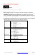
Eg. Get ID Bank 1 contains IDs 1 and 31, Set ID Bank 2 contains IDs 201 and 202, NDT3 contains the IDs
61 and 62 and the Series I RTU sending the data is RTU2.
Series I Data
Transfer
Get Bank
(1,31)
Set Bank
(201,202)
NDT
Override
Series 2 Storage
Locations
SDT to SDT 1 2 0 #NR2.201, #NR2.202
SDT to NDT 1 0 0 #NR2.1, #NR2.31
NDT to NDT 0 0 3 #NR3.61, #NR3.62
NDT to SDT 0 2 3 #NR3.201, #NR3.202
Polling Series I Data From A Series 2 RTU
When IDs are polled from a Series 2 RTU, the Series 2 RTU will reply with its own local registers (R1 to
R240) corresponding to the ID numbers. When an NDT is polled from a Series 2 RTU, the Series 2 RTU will
reply with the first 30 values from the network registers corresponding to the NDT number.
Communicating With A Kingfisher Series I RTU
When using a TX_CPU3 or an RX_CPU3 block the RTU should be configured as follows:
• First ensure that the latest firmware and Kingfisher Series 1 driver are loaded in the RTU (as detailed in
protocols.pdf available from www.cse-semaphore.com/mykingfisher).
• Set the port protocol as S1 Ctrl [controller] or S1 Outstn [outstation] in Configuration, Port List
depending on whether the Series 2 RTU is to act like a master or outstation Series I RTU. Note: the "No
CRC" port protocol option should only be selected when communicating with a CPU1 module over an
RS232 line.
• Set the port baudrate in Configuration, Port List.
• Add the address of the Series I RTU to the network list in Configuration, Network List (this must be a
unique address in the RTU network). Specify a system ID of AC Hex (for a CPU3 or CPU1 with version 3
EPROM) or A5 Hex (for CPU1 prior to version 3 EPROM).