
User manual


Toolbox 32 User Manual 1.47d www.cse-semaphore.com/mykingfisher
Page
147
Driver - Allen Bradley
Kingfisher RTUs communicate with Allen Bradley PLC's using the DF1 protocol in half duplex slave mode
with a 2-byte CRC. The data format is 8 data bits, 1 stop bit and no parity.
The Allen Bradley PLC returns an error code after each message. The error code is stored in the first
network register corresponding to the address assigned to the PLC. The STS error code is stored in the
lower 8 bits of the register and the EXT STS error code in the high 8 bits. A valid message will reset the
value to 0.
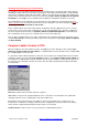
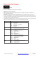
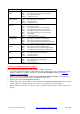
Tx Allen Bradley
Transmits up to 100 consecutive local registers from a Kingfisher RTU to an Allen Bradley PLC (PLC5 or
SLC500).
Comment: A 12-character description.
Station No. (decimal): (1-249) Station address configured in the Allen Bradley PLC. An Allen Bradley PLC
is treated like another RTU in the network. This means that the station address must be different to all the
other RTU addresses in the RTU's Network List.
Destination Register: Destination address in the Allen Bradley PLC where data is stored. This should be a
string reference like N10:1.
Source Register: (#R1 to #R1024) Local register of the RTU to read the data from.
No. Of Registers: (1-100) Number of 16-bit registers to send. Note: each floating point value uses two 16-bit
local registers. The maximum number of bytes that a message sent by an RTU can contain is 250. The
number of bytes sent varies depending on the contents of the message. In rare cases, the TX-AB message
can exceed this limit and so the message is not sent and an error code of 65535 is returned in the first
network register of the corresponding Station No RTU. It is therefore recommended that a maximum of 50
registers be written to the PLC in one message.
PLC Type: PLC5 / SLC500.