
User manual


Toolbox 32 User Manual 1.47d www.cse-semaphore.com/mykingfisher
Page
152
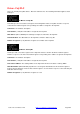
Response Codes (hexadecimal values)
Fuji Micrex-F
00 Processing is completed normally.
12 Data is written in program area.
20 Specified command code does not exist.
21 Input data does not sequence correlation to command. Example: Read or write by not using 4
byte units for 32-bit area.
22 Operation is available by loader only.
24 Module designated does not exist.
32 Oversized address for model number is designated.
A0 Communication module number error.
A1 Communication module busy.
A2 Exceeded number of data.
A3 Not suitable communication module.
A6 No data module.
A7 Unidentified boundary of data module to be transferred with receive byte number.
A8 Command error
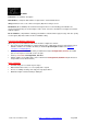
Fuji NJ PLC
00 Processing is completed normally.
01 Data is written to ROM.
02 Specified command code does not exist.
03 Inconsistent data (parameter error).
04 Processing is impossible due to transmission interlock by another device or loader.
05 Incorrect module No.
06 Search item not found.
07 An address exceeding the module's range was specified (during writing)
08 An instruction error was found in a writing program.
09 Program execution cannot continue due to an error.
0A After sending a WAK, a command other than cancel or continue was received.
0B Mismatched loader type (a command was sent to a loader that cannot be connected to the NJ
series PLC).
0C Mismatch password.
0E Connection to network is impossible.
0F Another loader is communicating over the network.
21 Now processing.
A7 Transmission error.
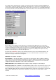
Communicating With A Fuji PLC
When using a TX/RX_MICREX or TX/RX_FUJI_NJ block the RTU should be configured as follows:
• First ensure that the Fuji driver is supported by the type of RTU that is being used and that the latest
firmware and driver are loaded in the RTU (as detailed in protocols.pdf available from www.cse-
semaphore.com/mykingfisher).
• Set the port protocol as Fuji Micrex-F or Fuji NJ-Series in Configuration, Port List.
• Set the port baudrate in Configuration, Port List. A serial port is used to communicate with a Fuji PLC.
• Add the address of the PLC to the network list in Configuration, Network List (this must be a unique
address in the RTU network).
• The Kingfisher RTU uses 8 data bits, no parity, 1 stop bit and CRC checking for communications with the
Fuji controller. To enable CRC checking on the communication messages, the Fuji controller needs to be
configured with an initialization file. The initialization table has to be defined in the ladder logic program
and the message module registration has to be setup.