
User manual


Toolbox 32 User Manual 1.47d www.cse-semaphore.com/mykingfisher
Page
256
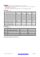
PSU-1 / PS-1
• PSU-1 Version 0: 24VDC output to backplane, includes an on board fan
• PSU-1 Version 1: 24VDC output to backplane, same as version 0 but does not have a fan and has a
different temperature measurement.
• PS-1: 12VDC or 24VDC output to backplane with processor controlled battery charging.
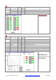
Digital Inputs
(ss = slot address 1-64)
Description PS-1 PSU1 V0 PSU1 V1
Read / Write
ON = AC Power ON #DIss.1 #DIss.1 #DIss.1
Read
ON = Aux 24V Failure / Not Present #DIss.2 #DIss.2 #DIss.2
Read
ON = Battery OK (OFF = battery low) #DIss.3 #DIss.3 #DIss.3
Read
ON = AC/DC operation (OFF=solar) N/A #DIss.4 #DIss.4
Read
ON = Temp > 50 deg C N/A N/A #DIss.9
Read
ON = Float State #DIss.5 N/A N/A
Read
ON = Charge State #DIss.6 N/A N/A
Read
ON = Boost State #DIss.7 N/A N/A
Read
ON = Temperature Sensor Error #DIss.8 N/A N/A
Read
ON = Battery is being charged
(Current into battery > 100mA)
N/A N/A N/A
Read
ON = Battery is being discharged
(Current out of battery > 60mA)
N/A N/A N/A
Read
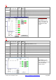
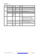
Digital Outputs
(ss = slot address 1-64)
Register
PS
-
1
PSU1 V0
PSU1 V1
#DOss.9 ON = Supply Voltage Trimming * ON = Fan ON
#
N/A
#DOss.10 ON = Supply Voltage Trimming * ON = Charge control off
#
ON = Charge control off
#
#DOss.11 ON = Supply Voltage Trimming * N/A N/A
#DOss.12 ON = Supply Voltage Trimming * N/A N/A
#DOss.13 ON = Supply Voltage Trimming * N/A N/A
#DOss.14
N/A
N/A N/A
#DOss.15
N/A
N/A N/A
#DOss.16 ON = Manual Trim Control
N/A N/A
* Supply Voltage Trimming (0-31). The number of voltage steps between the minimum and maximum DC output voltage.
For a 12V PS-1, there are 31 steps of approximately 100mV between 12 and 15 volts. For a 24V PS-1 there are 31 steps
of approximately 250mV between 24 and 32 Volts.
#
Only controllable during first 5 minutes after switching on.