
User manual


Toolbox 32 User Manual 1.47d www.cse-semaphore.com/mykingfisher
Page
23
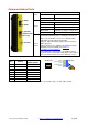
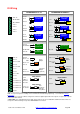
Digital Inputs
Digital Inputs 8 Max. Channels 5-8 can be configured as digital outputs.
Wakeup Functionality Channels 1 & 2 can wake the RTU on change of state if enabled
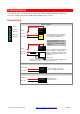
Pulse Counting
(digital inputs 1 and 2)
100 Hz max. in subactive powerdown mode
1 kHz max. in run mode
16-bit counter (can count up to 65535 pulses)
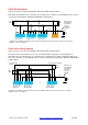
Configurable positive or negative edge counting
Pulse must be asserted for at least 0.5 ms in run mode or for 5 ms
in subactive powerdown mode.
OR
Negative Edge Counting Positive Edge Counting
0.5 ms min. 0.5 ms min.
Input Voltage Range
5.0 to 30 VDC = ON
0 to 1.0 VDC = OFF
Current Consumption <1 mA for all 8 inputs ON @ 5 VDC
Isolation None
Debounce
0 to 32,000 ms (configurable). Software debounced by reading 3
times and then accepting the change if all readings are the same
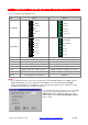
Digital Outputs
Relay Outputs Transistor Outputs
Digital Outputs 2
0 to 4
Up to 4 digital inputs can be
configured as sinking transistor
digital outputs
Relay Type
SPST-NO
(normally open)
Pulse output
Uses DO channel 3
0 to 65535 pulses
500 Hz maximum
Configurable pulse ON and OFF
times (0 to 65535 ms)
Maximum Switching voltage 30 VAC, 30 VDC 30 VDC
Maximum Switching Current 2 A 300 mA total for all 4 outputs
Maximum Switching Power 60 VA, 60 W
Isolation
Transient voltage: 500 V
Maximum working voltage in
respect to system earth/ground
must not exceed SELV limits
(42.4 Vpeak / 60 VDC)
No isolation
Operating Power 300 mW at 12 V
Fuse
300 mA fuse common for the 4
outputs
Effect of RTU power down Hold last state Last state restored on power up